AN4230 · Application noteIntroduction to random number generation validation using the NIST statistical test suite for STM32 MCUs and MPUs
Download .pdfOpen in the full document

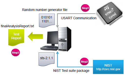
NISTSP800-22rev1a test suite steps

Step1: random number generator

Connect the STM32 board to the workstation. Depending on the type of board, the connection is made as follows:

  • via a null-modem female/female RS232 cable
  • via a USB Type-A to Mini-B cable

The STM32 RNG is run via the UART firmware in order to generate a random number as described in STM32MCU side. Data are stored on the workstation using a terminal emulation application such as a PuTTY (free and open-source terminal emulator, serial console and network file transfer application).

Step 2: NIST statistical test

The sts-2.1.1 package is compiled as described in the NIST statistical test suite documentation in order to create an executable program using visual C++ compiler.

After running the NIST statistical test suite program, a series of menu prompts are displayed in order to select the data to be analyzed and the statistical tests to be applied.

In this application note, the NIST statistical test suite is compiled under the name assess.exe and saved under the NIST_Test_Suite_OutputExample folder. As described previously, the random number is defined as 512,000 bits per block.

The various steps are detailed as follows:

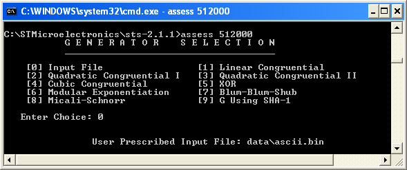
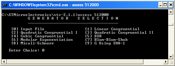
  1. The first screen that appears is shown below.
    Figure 4. Main sts-2.1.1 screen

    When value 0 is entered, the program requires to enter the file name and path of the random number to be tested.

  2. The second screen is shown below.
    Figure 5. File input screen

    This application note details an example with two files per series, generated with the STM32 RNG, with the following file formats as recommended by NIST:

    • ascii.bin: sequence of ASCII 0's and 1's
    • binary.bin: each byte in the data file contains 8 bits of data
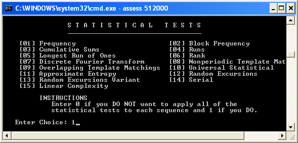
  3. The NIST statistical test suite displays 15 tests that can be run via the screen shown below.
    Figure 6. Statistical test screen

    In this case, 1 has been selected to apply all of the statistical tests.

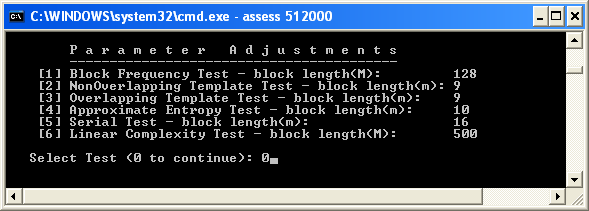
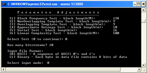
  4. The parameter adjustments ca be done in the screen shown below.
    Figure 7. Parameter adjustment screen

    In this example, the default settings are kept and value 0 is selected to go to the next step.

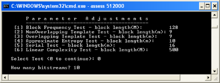
  5. The user needs to provide the number of bitstreams.
    Figure 8. Bitstream input

    The NIST statistical test suite requires to put the number of bitstreams: 10 is entered for this example, meaning 10 blocks of 512 Kbits are selected (5,12 Mbits).

  6. The user must then specify whether the file consists of bits stored in ASCII format or hexadecimal strings stored in a binary format using the following screen.
    Figure 9. Input file format

    Value 0 is selected because the file is in ASCII format.

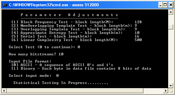
  7. After entering all necessary inputs, the NIST statistical test suite starts analyzing the input file.
    Figure 10. Statistical testing in progress
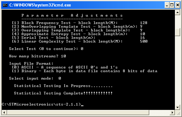
  8. When the testing process is complete, the screen below appears.
    Figure 11. Statistical testing complete

    The statistical test results can be found in sts-2.1.1\experiments\AlgorithmTesting.

Step 3: test report

The NIST statistical tests provide an analytical routine to facilitate the interpretation of the results. A file named

finalAnalysisReport is generated when the statistical testing is complete and saved under sts2.1.1\experiments\AlgorithmTesting.

The report contains a summary of experimental results of 15 tests (see NIST SP800-22rev1a statistical test suite).

The NIST statistical tests also provide a detailed report for each test, saved under

sts-2.1.1\experiments\AlgorithmTesting\<Test suite name>.

The two following examples of complete NIST statistical test suite output reports are available under

NIST_Test_Suite_OutputExample:
  • example of an Ascii_File_Format, with two folders:
    • Input_File: contains the random number generator saved with the ascii format.
    • Final_Analysis_Report: contains the complete NIST statistical test suite output report based on this input file, the summary of experimental results and the report of each test.
  • example of a Binary_File_Format, with two folders:
    • Input_File: contains the random number generator saved with the binary format.
    • Final_Analysis_Report: contains the complete NIST statistical test suite output report based on this input file, the summary of experimental results and the report of each test.

Cryptographic random bit overview

The cryptographic random bit generators (RBGs), also known as random number generators (RNGs), require a noise source that produces outputs with some level of unpredictability, expressed as min-entropy.

The specificity of the NIST SP800-90b statistical test suite is to probe the quality of random generators for cryptographic applications by its standardized means of estimating the quality of a source of entropy.

A comprehensive description of the suite is presented in the NIST document entitled Recommendation for the Entropy Sources Used for Random Bit Generation.

The NIST SP800-90b statistical test suite can be downloaded from the GitHub web site (https://github.com/usnistgov/SP800-90B_EntropyAssessment).

NIST SP800 90b test suite validation steps

The SP800-90B_EntropyAssessment C++ package implements the min-entropy assessment methods included in Special publication 800-90B.

To ensure that all the requirements for the NIST Special Publication (SP) 800-90 series recommendations are met it is necessary to validate the entropy source.

The general flow of entropy source validation testing is summarized in the steps below:
  1. Data collection.
  2. IID track or non IID track.
  3. Initial entropy estimate.
  4. Restart tests.
  5. Entropy estimation for entropy sources using a conditioning component.
  6. Additional noise sources.
The project is composed of two separate sections:
  • -non-IID tests: provide an estimate for min-entropy, called Horiginal, for any data provided (the STM32 certifiable TRNG noise source is tested using non-IID tests)
  • -ea-restart tests: check the relations between noise source samples generated after restarting the entropy source, and compare the results to the initial entropy estimate HI
Note:

HI = min (Horiginal, Hsubmitter) for binary sources where Hsubmitter is the entropy estimate provided based on the submitter’s analysis of the noise source.

Data collection description

Random datasets are extracted from STM32-RNG peripheral entropy sources using the interrupt method (see AN4230_STM32-Firmware-description.html#id_36750__fig_ucv_5yg_wqb). The USART is used to send the generated raw data to the workstation to be tested with the NIST statistical test suite.

  • 1,024,000 random samples are generated continuously from the RNG peripheral with the conditioning stage deactivated. Then it is shortened to keep exactly 1,000,000 samples. Sampled data are converted to binary in order to respect the format required by NIST SP800-90b tool suite. These binaries are used for the continuous tests.
  • 1024 x 1000 random samples are extracted with restart at every 1000 bits extracted. They are then shortened to get 1000 x1000 samples as recommended by NIST. In restart extraction, 1000 unconditioned samples are collected directly from the noise source by disabling/enabling the RNG for each restart among the 1024 restarts required.

This random dataset can be extracted either with collecting continuous bits without disabling the RNG module or with restarting the RNG at every 1000 bits. The output file format is a sequence of hexadecimal digits in ASCII format, which is converted to binary format without alteration of data using a small Python script. This way, random bits are ready to be processed by NIST tests suite in *.bin dataset format.

An STM32 USART peripheral is configured to establish USB communication between the STM32 board and a workstation.

Interruption extraction mode
  • Two extraction modes are performed, with restart at every 1000 bits and continuous without restart:
    • When 1000 x 1024 restart dataset is to be extracted, the following macros definitions are considered.
      /* number of random bits*/
      #define NUMBER_OF_RANDOM_BITS	   1024  						
      /* number of 32bits words*/
      #define NUMBER_OF_RANDOM_32_BITS   NUMBER_OF_RANDOM_BITS /32
      /* number of restarts */ 		
      #define BLOCK_NUMBER 			   1000
    • When continuous 1,024,000 dataset bits are to be extracted, the following macros definitions are considered.
      
      /* number of random bits*/
      #define NUMBER_OF_RANDOM_BITS	   1024*1000  					
      /* number of 32bits words*/
      #define NUMBER_OF_RANDOM_32_BITS   NUMBER_OF_RANDOM_BITS /32  		
      /* number of restarts */
      #define BLOCK_NUMBER 			   1   
      
Note:

In continuous extraction mode, the size of a block is set to 1,024,000 and the number of blocks is set to 1, so that the RNG is disabled only after the generation of the entire dataset.

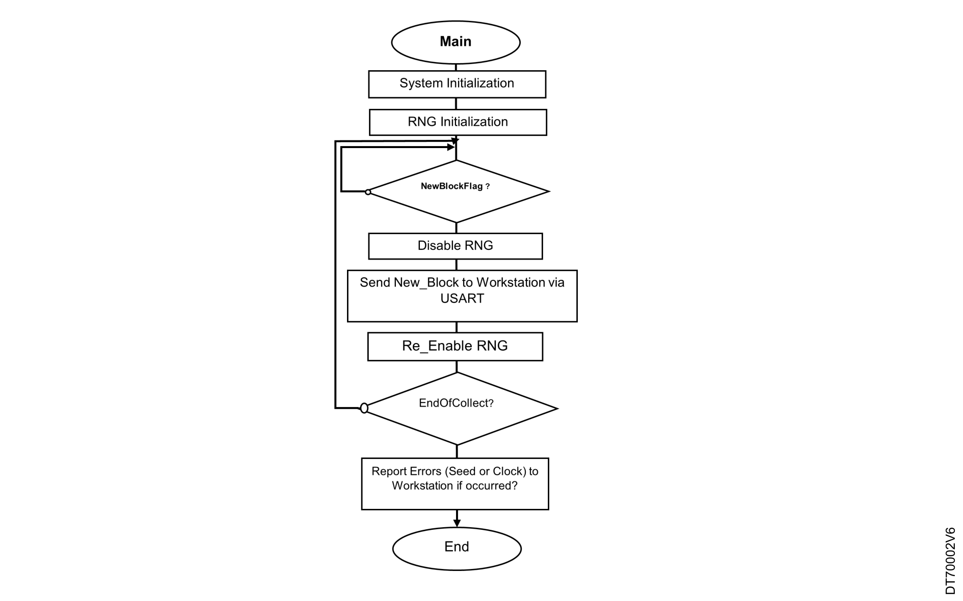
  • CPU system modules, PLL clocks, and peripherals used within the system are configured in the system initialization (see Figure 12 Main function in interrupt mode).
  • The RNG initialization function sets the RNG bypass bit in the control register. This allows random bits to be extracted directly from the noise source without using the conditioning block. The function also enables the health test module by programming the HTCR register with appropriate values. In addition, the function activates the RNG module and configures the RNG interrupt.
  • After a hardware reset, the main program waits until a 1‑Mbit block is filled with random bits before sending the data to the workstation. The extraction occurs in quad‑words (128 bits). When the DRDY flag is set, the RNG_DR register is read four times to ensure that 128 new successive random bits are extracted. When the number of blocks reaches the maximum value, the system stops execution and stores the 1‑Mbit random dataset in a log file on the workstation.
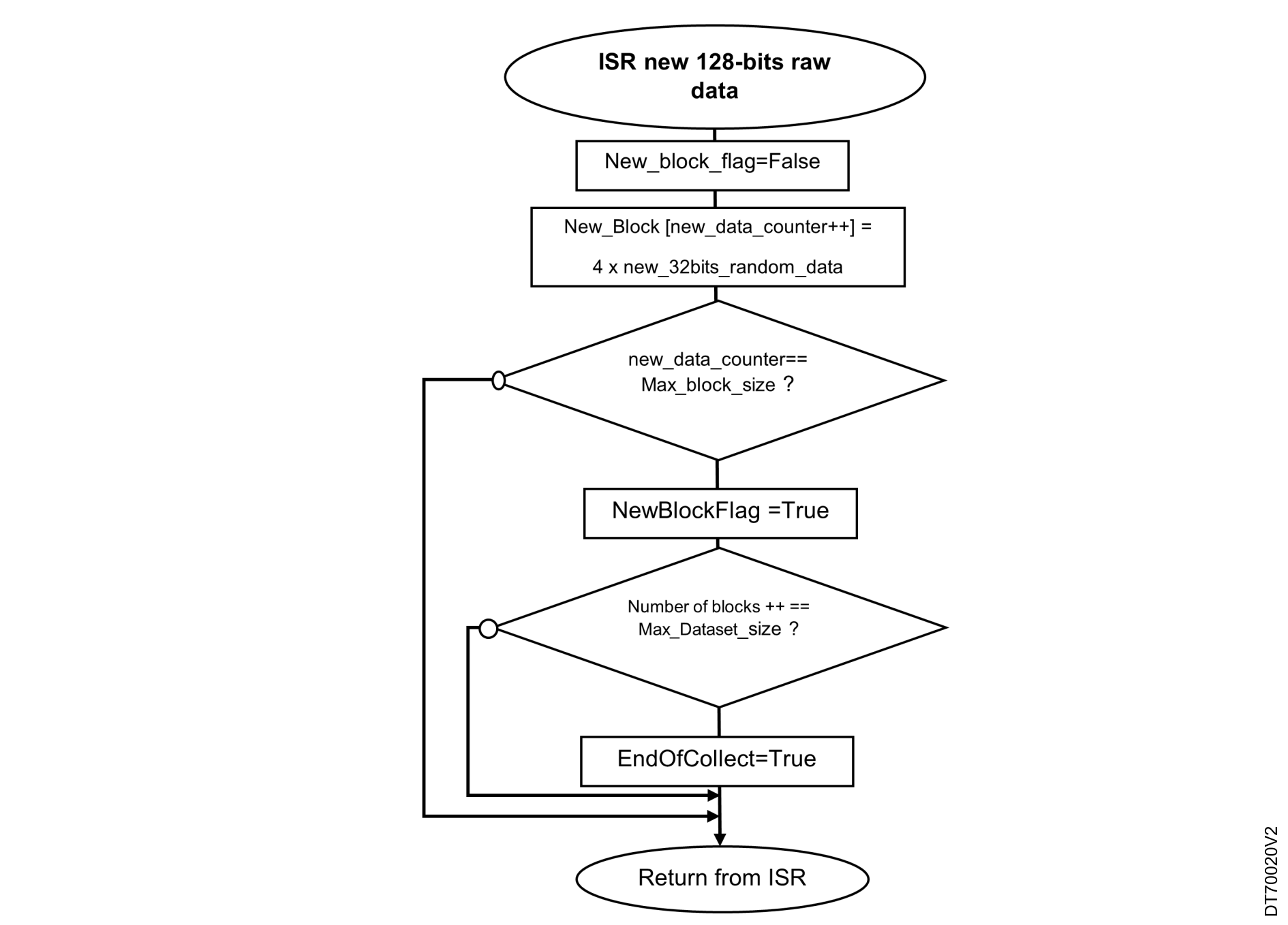
  • When the interrupt enable (IE) bit is set in the RNG control register (RNG_CR), the RNG triggers an interrupt each time new 32-bit random data is available in the RNG data register (see Figure 13 ISR callback function when DRDY interrupt flag is set). The RNG status flag DRDY remains high until the output buffer is empty after reading four words from the RNG_DR register. This operation is performed within the RNG callback function (HAL_RNG_ReadyDataCallback) which extracts four 32-bit raw data words.
  • The block size depends on the extraction mode: 1 Mbit in continuous mode, and 1024 bits in restart mode. When a block of the configured size is completed and the maximum number of blocks is reached, two user flags are set: NewBlockFlag and EndOfCollect. The main function monitors these flags to control data transmission to the workstation.
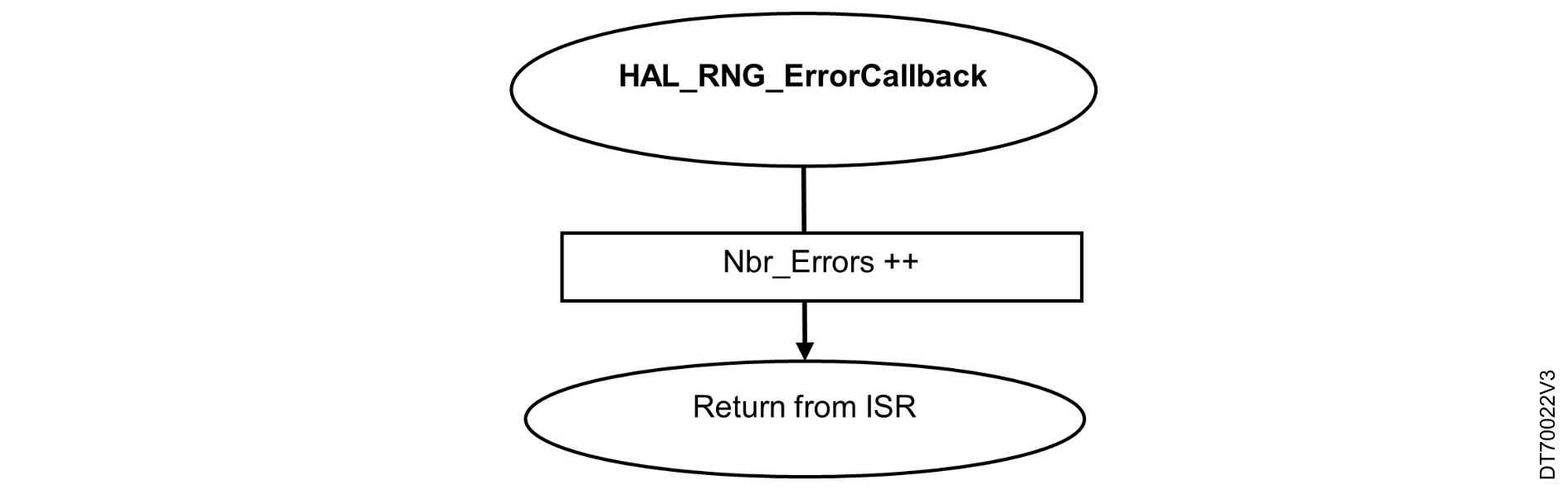
  • When interrupts are enabled, a second callback function (HAL_RNG_ErrorCallback) is triggered if the RNG detects a seed or clock error. An error counter is then incremented, the RNG is restarted, and the extraction of the current data set is aborted (see Figure 14 ISR callback function when Error-flag).
  • Note that the HTCR value is characterized for NIST certification to minimize the seed errors without causing any clock errors. In this experimentation, no seed errors were detected during extraction according to this HTCR value.
Figure 12. Main function in interrupt mode
Figure 13. ISR callback function when DRDY interrupt flag is set
Figure 14. ISR callback function when Error-flag
Pooling extraction mode
The STM32 devices can be programmed in polling mode to extract raw datasets from the RNG peripheral. Configure the device as follows:
  • CPU system modules, PLL clocks, and the peripherals used in the system are configured in the system initialization function shown in Figure 15 Continuous extraction mode and Figure 16 Restart extraction mode.
  • The RNG initialization function sets the RNG bypass bit in the control register. This allows random bits to be extracted directly from the noise source without using the conditioning block. The function also activates the health test module by writing appropriate values to the HTCR register.
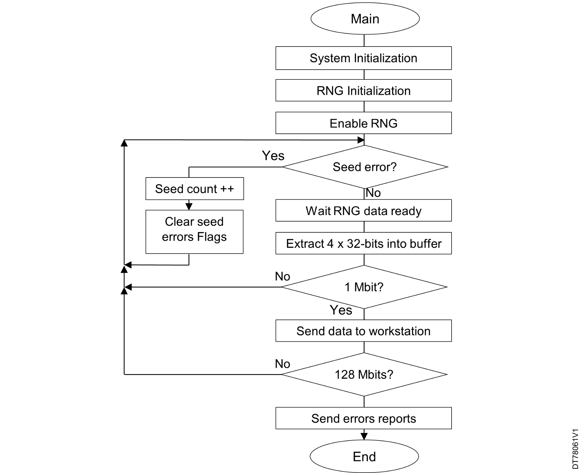
  • Continuous extraction mode (Figure 15 Continuous extraction mode): After a hardware reset, the main program waits until a block of 1 Mbit of random data is generated before sending the data to the workstation. The program extracts data in quad‑words (128‑bit blocks). Each time the DRDY flag is set, the program reads the RNG_DR register four times to ensure that 128 new consecutive random bits are collected. After generating and transferring 128 Mbits to the workstation, the program also sends the total number of seed errors.
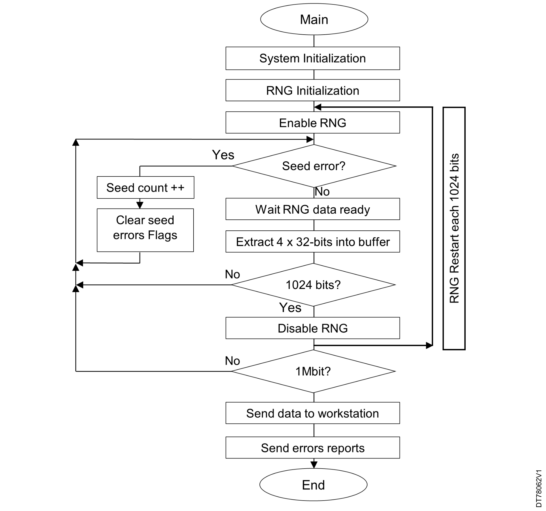
  • Restart extraction mode (Figure 16 Restart extraction mode): In restart extraction mode, the program disables the RNG peripheral after every 1024 bits are extracted, then re-enables the peripheral to continue generation until a total of 1 Mbit is collected. The program then sends this 1‑Mbit block to the workstation, along with the reported number of seed errors.
Figure 15. Continuous extraction mode
Figure 16. Restart extraction mode
How to configure the RNG NIST Compliant configurations

The STM32Cube HAL RNG driver is used to configure the RNG with a NIST‑compliant setup. This driver provides the RNG_ConfigTypeDef structure and the HAL_RNGEx_SetConfig() API to customize the RNG configuration.

In the following code example, the RNG peripheral of the STM32U54x is configured according to the NIST‑compliant settings published by NIST for the STM32U545 public use entry (#E158).

First, the NIST‑compliant configuration is stored in a firmware structure named

sRngNistConfigU545, initialized as shown below. The first five fields map to the RNG_CR register bits (bit ranges indicated in the comments). The sixth and seventh fields hold the values for the RNG_HTCR and RNG_NSCR registers.
RNG_ConfigTypeDef sRngNistConfigU545 =
{
   .Config1       = 0x0F,             /* RNG_CR[27:20]      */
   .Config2       = 0,                /* RNG_CR[15:13]      */
   .Config3       = 0xF,              /* RNG_CR[11:8]       */
   .ClockDivider  = 0x1,              /* RNG_CR[19:16]      */
   .NistCompliance= RNG_CR_NISTC,     /* RNG_CR[12] bit NISTC = 1 */
   .HealthTest    = 0x76B3,           /* RNG_HTCR register  */
   .NoiseSource   = 0x24C2,           /* RNG_NSCR register  */
   .AutoReset     = RNG_ARDIS_ENABLE,
};
In the main function, the HAL_RNGEx_SetConfig() API is called to apply this NIST‑compliant configuration to the RNG peripheral.
if (HAL_RNGEx_SetConfig(&hrng, &sRngNistConfigU545) != HAL_OK)
{
  /* ERROR: RNG SET CONFIG FAILED */
}
NIST compliant RNG configuration

The table below summarizes the RNG configuration values that are recommended for the entropy source to be compliant with NIST SP 800‑90B. Those configurations correspond to an RNG clock of 48 MHz. The certificate column indicates when the configuration values are part of a NIST SP800-90B CMVP certification.
Table 3. RNG register values

Product(1)RNG_CR value(2)HTCR valueNSCR valueCertificate(3)
STM32L4P/Q0x00F00D000xAA74default-
STM32L50x00F00D000xA2B3default-
STM32U073x/83x0x08F01E000x66830x003FYes
STM32U575/5850x00F00D000xA2B00x17CBBYes
STM32U59x/5Ax0x00F11F000x92F30x1609Yes
STM32U535/5450x00F11F000x76B30x24C2Yes
STM32U5Fx/5Gx0x00F11F000xA7150x9049Yes
STM32H7Rx/7Sx0x08F01E000x6a920x2F83FYes
STM32H7A3/7B30x00F00D000x72ACdefault-
STM32H72x/73x0x00F00D000xAA74default-
STM32WLx0x00F00D000xAA74default-
STM32H5030x00F00D000xAAC7default-
STM32H523/5330x08F01E000x066890x2357FYes
STM32H543/5530x0845 1F00 0xAAC7default-
STM32H563/573/5620x00F01E000x6A910x3AF66Yes
STM32H5Ex/5Fx0x08451F000xAAC7 default-
STM32WBA5x0x08F01F000x66880x0FFFYes
STM32MP13x0x00F00D000x668A0x2B5BBYes
STM32MP25x0x08F01E000x66880x2E649Yes
STM32U375/3850x08351F000x6A8B0x01FF-
STM32N60x08F00D000x6A93(4)default-
STM32WBA6x0x08401F000x6EA0 0x01FFYes
STM32MP21x0x08451F000x6A8C(4)0x1DF-
STM32C5x0x08451F000x66840x01BF-
Table 4. NIST SP800-90B certificates

ProductSP800-90B entropy source certificateNIST public use document
STM32U575/585#E11(5)E11 public use(5)
STM32U5Fx/5Gx#E116(5)E116 public(5)
STM32U59x/5Ax#E135(5)E135 public(5)
STM32U535x/545x#E158E158 public(5)
STM32H56x/573#E163(5)E163 public(5)
STM32MP13x#E53(5)E53 public use(5)
STM32WBA5x#E186(5)E186 public(5)
STM32U073x/83x#E262(5)E262 public(5)
STM32H7Rx/7Sx #E255(5)E255 public(5)
STM32H523/533#E283(5)E283 prblic(5)
STM32MP25x#228(5)E228 public(5)
STM32WBA6x#299(5)E299 public(5)
Note:

Entropy results can be shared with customers when required.

1 A special device must be used to execute the NIST test suite, except for the STM32L4P/Q, STM32H7A3/7B3, and STM32H72x/73x.
2 The bit 6 of RNG_CR enables or disables the bypass of post‑processing/conditioning logic. This bit must be enabled to run the NIST SP800‑90B test suite.
3 "Yes" indicates when the configuration values are part of an official NIST SP800-90B certificate. Links to these certificates can be found in Table 4 NIST SP800-90B certificates.
4 This URL belongs to a third party. It is active at document publication, however STMicroelectronics shall not be liable for any change, move, or inactivation of the URL or the referenced material.
5 The HTCR value programmed in the product OTP fuse configuration (rng_htcr_value) applies only to the boot ROM. Because the OTP selection supports only a restricted set of HTCR values, set rng_htcr_value to 0x6, which corresponds to HTCR = 0xAAC7. The user application can then use the HTCR value provided in Table 3 RNG register values.
6 A special device must be used to execute the NIST test suite, except for the STM32L4P/Q, STM32H7A3/7B3, and STM32H72x/73x.
7 The bit 6 of RNG_CR enables or disables the bypass of post‑processing/conditioning logic. This bit must be enabled to run the NIST SP800‑90B test suite.
8 "Yes" indicates when the configuration values are part of an official NIST SP800-90B certificate. Links to these certificates can be found in ***.
9 The HTCR value programmed in the product OTP fuse configuration (rng_htcr_value) applies only to the boot ROM. Because the OTP selection supports only a restricted set of HTCR values, set rng_htcr_value to 0x6, which corresponds to HTCR = 0xAAC7. The user application can then use the HTCR value provided in ***.
10 This URL belongs to a third party. It is active at document publication, however STMicroelectronics shall not be liable for any change, move, or inactivation of the URL or the referenced material.