AN4879 · Application noteIntroduction to USB hardware and PCB guidelines using STM32 MCUs
Download .pdfOpen in the full document

Supported USB speeds

Supported USB speeds

In Host mode, the USB OTG_FS supports full- and low-speed transfers, while in device mode it only supports full‑speed transfers.
Table 7. Supported OTG_FS speeds
Mode1FS (12 Mbit/s)LS (1.5 Mbit/s)
HostXX
DeviceX-
In Host mode, the USB OTG_HS supports high-, full-, and low-speed transfers, while in device mode, it only supports high- and full-speed transfers.
Table 8. Supported OTG_FS speeds
Mode2HS (480 Mbit/s)FS (12 Mbit/s)LS (1.5 Mbit/s)
HostXXX
DeviceXX-
1 X: supported.
2 X: supported.

Protection against ESD and EMI

Protection against ESD and EMI is needed. The system must comply with both the JESD22-A114D (also known as HBM) and the IEC 61000-4-2 standards.

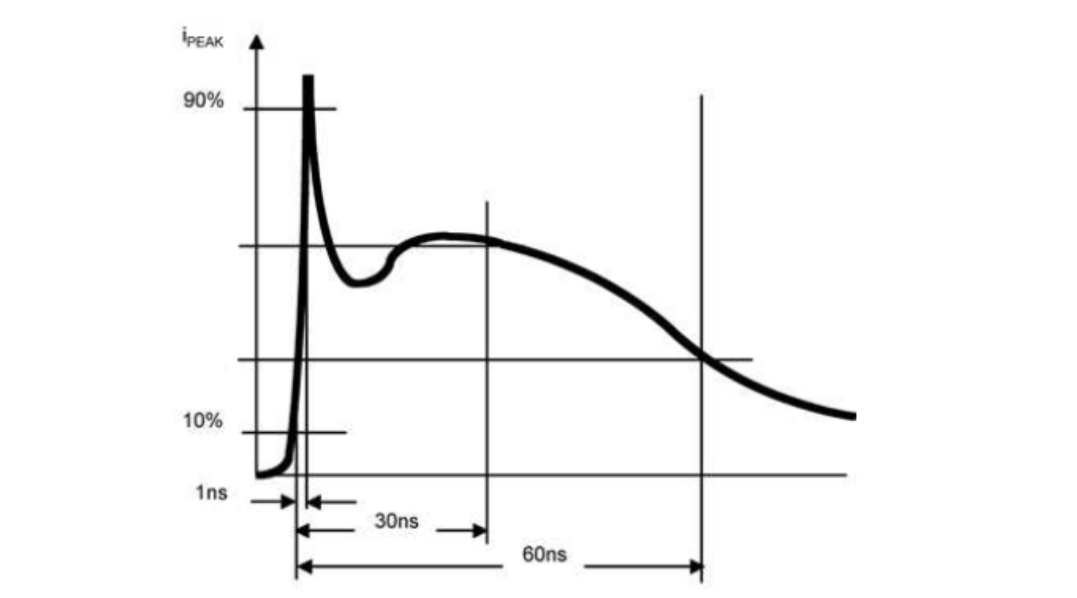
The HBM requires that the USB pins of the component device be tolerant up to 2 kV discharge, this is the case for STM32 MCUs. Refer to the figure and the table below for JESD22-A114D standard test waveform and class levels. For more details, refer to the document System Level ESD-expanded available at www.jedec.org.
Figure 1. JESD22-A114D standard test waveform


Table 9. JESD22-A114D standard class levels
ClassVoltage rangeCurrent range
Class 0V < 250 VI < 0.17 A
Class 1A250 V < V < 500 V0.17 A < I < 0.33 A
Class 1B500 V < V < 1000 V0.33 A < I < 0.67 A
Class 1C1 kV < V < 2 kV0.67 A < I < 1.33 A
Class 22 kV < V < 4 kV1.33 A < I < 2.67 A
Class 3A1 kV < V < 8 kV2.67 A < I < 5.33 A
Class 3BV > 8 kVI > 5.33 A
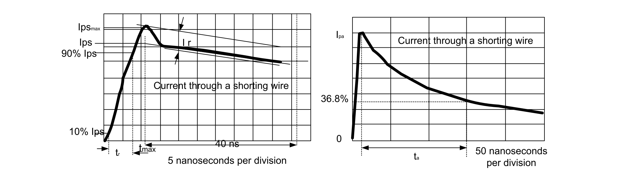
The system must also comply with the IEC 61000-4-2 standard on USB lines when they are connected to a receptacle. This standard is fairly different from the HBM standard. Refer to the image and the table below for IEC 61000-4-2 standard test waveform and class levels.
Figure 2. IEC 61000-4-2 standard waveform


Table 10. IEC 61000-4-2 standard class levels
LevelContactAirPeak current (A)
Indicated voltage (kV)
1237.5
24415
36822.5
481530

To see the difference between the current pulses applied in the two tests, compare the two figures presented above.

To improve the protection against high ESD surges (and then to meet the conditions requested by the standards), dedicated components have to be placed as close as possible to the receptacle (see the table below).
Table 11. ESD protection
InterfaceProtection
Low priceLow area on PCB
USB FS

USBLC6-2SC6

(+ ESDA7P60-1U1M for VBUS)

USBLC6-2P6

(+ ESDA7P60-1U1M for VBUS)

USB FS OTGUSBLC6-4SC6DSILC6-4P6
USB HSECMF02-2AMX6 (+ ESDA7P60-1U1M for 5 V VBUS)
USB HS OTG ECMF02ECMF02-2AMX6 (+ ESDA7P60-1U1M for 5 V VBUS + ESDALC6V1-1U2 for ID)

Clock

The FS USB device/OTG requires a precise 48 MHz clock. This frequency can be generated from the internal main PLL, or by the internal 48 MHz oscillator.

In the first case, the clock source must use an HSE crystal oscillator, in the second case, the synchronization for the oscillator can be taken from:
  • The USB data stream itself (SOF signalization), no external resonator/ crystal is needed (this feature is only available for devices embedding a crystal-less USB 2.0 FS device interface), or
  • The internal 48 MHz oscillator trimmed on LSE (not accurate enough for a USB host).
  • MSI and LSE only for STM32L47x/L48x devices.

If HS operation is required, the OTG PHY is connected to the microcontroller ULPI port through 12 signals. It can be clocked using the 60 MHz output (provided from the HS PHY: HSE is not mandatory in this case).

As stated on the following figure, for STM32F7x3xx devices the USB HS PHY includes two embedded PLLs:
  • PLL1: has as clock source the HSE clock. The supported values are: 12, 12.5, 16, 24 and 25 MHz. The PLL1 outputs the 60 MHz used as input for the PLL2.
  • PLL2: outputs the high speed (480 MHz) clock.
Figure 3. HS PHY PLLs on STM32F7x3 devices


Note:

The AHB frequency has to be higher than 14.2 MHz to guarantee a correct operation for the USB OTG_FS peripheral, and higher than 30 MHz for the USB OTG_HS peripheral.

Power

For USB transceivers, the operating voltage ranges between 3.0 and 3.6 V. This voltage is obtained from one of the following:
  • VDD: standard external power supply for the STM32MCU I/Os
  • VDDUSB: a dedicated independent power supply for USB. This power supply can be connected either to VDD or to an external independent power supply for USB transceivers.

Consequently, the microcontroller can be powered with the minimum specified supply voltage, while an independent power supply 3.3 V can be connected to VDDUSB.

When the VDDUSB is connected to a separated power supply, it is independent from VDD or VDDA, but it must be the last supply to be provided and the first to be removed.

Some important points to notice are listed below:
  • The USB full-speed transceiver functionality is ensured down to 2.7 V. The USB full-speed electrical characteristics are degraded when VDD ranges between 2.7 and 3.0 V
  • VDDUSB is not available on all STM32 devices. Refer to the "Dedicated VDDUSB" column in AN4879_USB-on-STM32-products.html#id_3644__table_irq_4n2_5fb to check whether this feature is available on a specific MCU.
  • The VDDUSB pin must be connected to two external decoupling capacitors (100 nF ceramic + 1 μF tantalum or ceramic)
  • Some devices, when in high-pin-count packages, feature a dedicated VDDUSB pin. When assembled in low‑pin‑count packages, these devices have only the VDD pin to ensure the USB functionality.
  • On STM32F7x3xx devices, the USB HS PHY subsystem uses an additional power supply pin: VDD12OTGHS pin is the output of the HS PHY regulator (1.2 V). An external capacitor (2.2 μF) must be connected to the VDD12OTGHS pin.
  • On STM32H7x3 devices, VDD50USB can be supplied through the USB cable to generate the VDD33USB via a USB internal regulator. This is used to support a VDD supply different from 3.3 V. The USB regulator can be bypassed to supply VDD33USB directly when VDD = 3.3 V.
Note:

Refer to AN5419, 'Getting Started with STM32H723/733, STM32H725/735, and STM32H730 Value Line Hardware Development,' for more details about the STM32H7 power supply configuration in USB.