AN4908 · Application noteGetting started with USART automatic baud rater detection for STM32 MCUs
Download .pdfOpen in the full document

Automatic baud rate detection modes

Automatic baud rate detection modes

ABR refers to the process by which a receiving device determines the speed of incoming data by examining the first character, usually a preselected sign-on character.

The automatic baud rate feature on STM32 products embeds various modes based on different character patterns:

  • Any character starting with a bit at ‘1’: Mode 0
  • Any character starting with a 10xx pattern: Mode 1
  • 0x7F: Mode 2
  • 0x55: Mode 3
Table 7. Automatic baud rate detection modes
ABR modeDescriptionWaveform
0

The received character can be a character starting with a bit at 1. In this case, the USART measures the duration of the start bit (falling edge to rising edge).


1

Any character starting with a 10xx pattern. In this case, the USART measures the duration of the start and of the first data bit. The duration is measured from falling edge to falling edge, ensuring better accuracy in the case of slow signal slopes.


2

0x7F character frame.

In this case, the baud rate is updated first at the end of the start bit then at the end of the bit 6.


3

A 0x55 character frame.

In this case, the baud rate is updated first at the end of the start bit, then at the end of bit and finally at the end of bit 6. In parallel, another check is performed for each intermediate transition of the RX line.


Before activating the automatic baud rate detection, one of the ABR modes must be selected through the ABRMOD[1:0] field in the USARTx_CR2 register. In all ABR modes, the baud rate is measured several times during the synchronization data reception, and is compared each time to the previous measurement.

Note:

In 7-bit data length mode, 0x7F and 0x55 frames detection ABR modes are not supported.
Error calculation for ABR

The USART clock source (fCK) determines the communication speed range (specifically the maximum communication speed). The receiver implements different user-configurable oversampling techniques for data recovery by discriminating between valid incoming data and noise. This allows a trade-off between the maximum communication speed and immunity to noise/clock inaccuracy.

The oversampling method is selected by programming the OVER8 bit in the USARTx_CR1 register, and can be either 16 or 8 times the baud-rate clock.

The USART clock source frequency must be compatible with the expected communication speed:

  • When oversampling by 16, the baud rate is between fCK/65535 and fCK/16

  • When oversampling by 8, the baud rate is between fCK/65535 and fCK/8.

The baud-rate error is dependent on the USART clock source, the oversampling method, and the ABR mode.

Error(%) = |desired⁢ baud⁢ rate⁢−actual⁢ baud⁢ ratedesired⁢ baud⁢ rate|⋅ 1001

Where:

  • The desired baud rate is fixed by the transmitter device.

  • The actual baud rate is the baud rate determined by the USART receiver using the automatic baud rate detection operation.

Software automatic baud rate detection

When hardware auto baud rate detection is not supported, the software approach described in this section can be adopted.

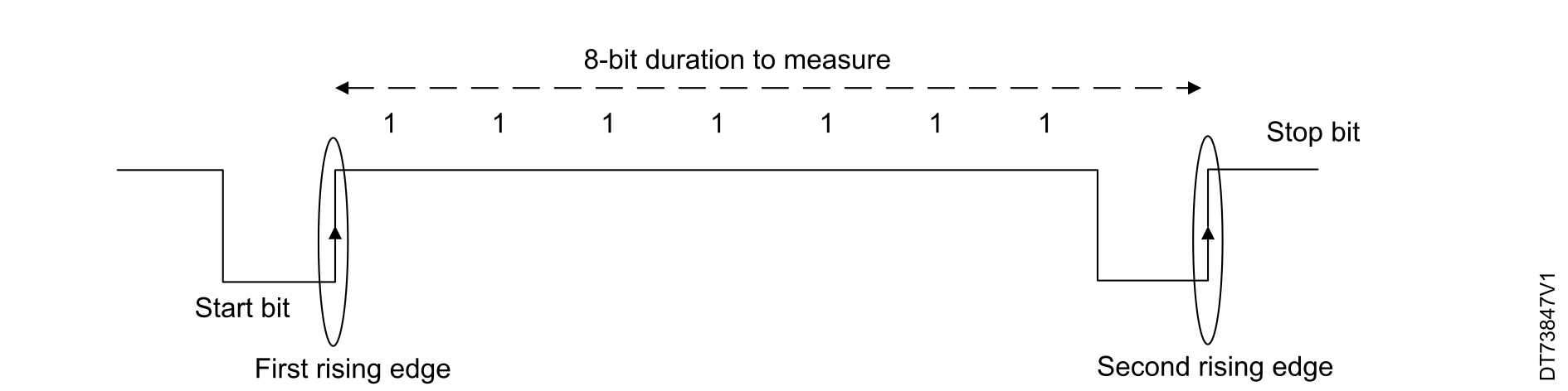
The idea of the software approach is to send a 0x7F data frame to the USARTx_RX pin. This is connected to the EXTI line, which is configured to generate an interrupt on each rising edge.

The duration of the interval between the two rising edges is measured using the SysTick timer. This duration corresponds to the duration of 8 bits, so

  • Bit time = calculated duration/8

  • Baud rate = 1/bit time

The USARTx_BRR register is then programmed, based on the calculated baud rate value.

Figure 1. Software automatic baud rate detection overview


Setups for software and hardware approaches

The STM32F303xD/E embedding the hardware automatic baud rate feature is used for this setup example.

The HyperTerminal PC application is used to send and receive data frames to and from the STM32F303. Consequently, standard baud rates in the range 600 bits/s to 115200 bits/s are tested. The highest baud-rate value that can be reached (9 Mbits/s) is tested using another STM32F3 device as a transmitter.

USART1 configuration example

In both examples, the STM32 USART1 is configured as follows:

/*##-1- Configure the UART peripheral
######################################*/
/* Put the USART peripheral in the Asynchronous mode (UART Mode) */
/* UART configured as follows:
- Word Length = 8 Bits
- Stop Bit = One Stop bit
- Parity = NONE parity
- BaudRate = 115200 baud It can be any other value as the USARTx_BRR
register will be reprogrammed
- Hardware flow control disabled (RTS and CTS signals)
- The oversampling mode is 8 or 16 (Both are tested)
*/
UartHandle.Instance = USARTx;
UartHandle.Init.BaudRate = 115200;
UartHandle.Init.WordLength = UART_WORDLENGTH_8B;
UartHandle.Init.StopBits = UART_STOPBITS_1;
UartHandle.Init.Parity = UART_PARITY_NONE;
UartHandle.Init.HwFlowCtl = UART_HWCONTROL_NONE;
UartHandle.Init.Mode = UART_MODE_TX_RX;
UartHandle.Init.OverSampling = UART_OVERSAMPLING_16;
Note:

The USART1 clock source is a system clock at 72 MHz using the HSE PLL clock source. Some tests are made using the HSI clock as the USART1 clock source. This is to check the impact of the HSI inaccuracy on the results.

Hardware auto baud rate detection

The USART1 is configured to detect baud rate automatically. The user has to select the ABR mode in the USART1 initialization function as follows:

/*##-2- Configure the AutoBaudRate method */
UartHandle.AdvancedInit.AdvFeatureInit =UART_ADVFEATURE_AUTOBAUDRATE_INIT;
UartHandle.AdvancedInit.AutoBaudRateEnable =
UART_ADVFEATURE_AUTOBAUDRATE_ENABLE;
/*Uncomment your appropriate mode */
//UartHandle.AdvancedInit.AutoBaudRateMode =
UART_ADVFEATURE_AUTOBAUDRATE_ONSTARTBIT;
//UartHandle.AdvancedInit.AutoBaudRateMode =
UART_ADVFEATURE_AUTOBAUDRATE_ONFALLINGEDGE;
//UartHandle.AdvancedInit.AutoBaudRateMode =
UART_ADVFEATURE_AUTOBAUDRATE_ON0X7FFRAME;
//UartHandle.AdvancedInit.AutoBaudRateMode =
UART_ADVFEATURE_AUTOBAUDRATE_ON0X55FRAME;
if (HAL_UART_Init(&UartHandle) != HAL_OK)
{
/* Initialization Error */
Error_Handler();
}
/* Wait until Receive enable acknowledge flag is set */
while(__HAL_UART_GET_FLAG(&UartHandle,UART_FLAG_REACK) == RESET)
{}
/* Wait until Transmit enable acknowledge flag is set */
while(__HAL_UART_GET_FLAG(&UartHandle,UART_FLAG_TEACK) == RESET)
{}
/* Loop until the end of Autobaudrate phase */
while(__HAL_UART_GET_FLAG(&UartHandle,UART_FLAG_ABRF) == RESET)
{}

Once the whole initialization is complete, the USART waits until data is received from the HyperTerminal before launching the automatic baud rate detection phase. The end of this phase is monitored by the ABRF flag.

  • If the auto baud rate operation is unsuccessful, the ABRE flag is set
  • If the auto baud rate operation is completed successfully, an acknowledgment data is transmitted to the HyperTerminal.
/* If AutoBaudBate error occurred */
if (__HAL_UART_GET_FLAG(&UartHandle, UART_FLAG_ABRE)!= RESET)
{
Error_Handler();
}
else
{
/* Wait until RXNE flag is set */
while(__HAL_UART_GET_FLAG(&UartHandle,UART_FLAG_RXNE) == RESET)
{}
/* Send acknowledgement message*/
if (HAL_UART_Transmit_DMA(&UartHandle, (uint8_t *)aTxBuffer, TXBUFFERSIZE)
!= HAL_OK)
{
/* Transfer error in transmission process */
Error_Handler();
}
while (HAL_UART_GetState(&UartHandle) != HAL_UART_STATE_READY)
{
}
}

Software automatic baud rate detection

Table 8 Software automatic baud rate detection details details the software approach.

Table 8. Software automatic baud rate detection details
ActionCode

HAL library initialization. Suspend Tick increment to prevent wake-up by SysTick interrupt.

HAL_Init();
HAL_SuspendTick();

Configure the system clock to 72 MHz.

The SystemCoreClockUpdate function can eventually be executed in the main to verify the CPU operating frequency.

System Clock source = PLL (HSE)
PLLMUL = RCC_PLL_MUL9 (9)
Flash Latency(WS) = 2

Configure the UART peripheral.

See USART1 configuration example.

Configure the USARTx RX pin to generate an interrupt on each rising edge.

static void EXTILine1_Config(void)
{
GPIO_InitTypeDef GPIO_InitStructure;
/* Enable GPIOE clock */
__GPIOE_CLK_ENABLE();
/* Configure PE1 pin as input floating */
GPIO_InitStructure.Mode = GPIO_MODE_IT_RISING;
GPIO_InitStructure.Pull = GPIO_NOPULL;
GPIO_InitStructure.Pin = GPIO_PIN_1;
HAL_GPIO_Init(GPIOE, &GPIO_InitStructure);
/* Enable and set EXTI Line0 Interrupt to the lowest
priority */
HAL_NVIC_SetPriority(EXTI1_IRQn, 2, 2);
HAL_NVIC_EnableIRQ(EXTI1_IRQn);
}

0x7F received on RX pin, wait until the end of the interrupt.

Launch the automatic baud rate sequence described in Software automatic baud rate detection.

/*Wait until the end of interrupt */
while (end_interrupt_flag != 1) {
BSP_LED_On(LED2);
}
/* Autobaudrate sequence : Update BRR register */
Autobaudrate();
/* Send acknowledgement */
if (HAL_UART_Transmit_DMA(&UartHandle, (uint8_t
*)aTxBuffer, TXBUFFERSIZE) != HAL_OK)
{
/* Transfer error in transmission process */
Error_Handler();
}
while (HAL_UART_GetState(&UartHandle) !=
HAL_UART_STATE_READY)
{}
/* Infinite loop */
while (1)
{}
Automatic baud rate function
static void Autobaudrate(void)
{
float tmp=0, elapsed;
uint32_t USART1_clk=0;
uint32_t start_time_val=0;
uint32_t BRR=0;
tmp += 0xFFFFFF - stop_time_val;
tmp -= start_time_val;
elapsed =(tmp/(SystemCoreClock/1000000))/8;
USART1_clk=SystemCoreClock;
if( (USART1->CR1 & 0x8000)== 0x8000)
{
/*In case of oversampling by 8*/
BRR =(elapsed*((2*USART1_clk)/1000000))+1;
USART1->BRR= BRR;
}
else
{
/*In case of oversampling by 16*/
BRR =(elapsed* ((USART1_clk)/1000000))+1;
USART1->BRR=BRR;
}
}

External line 1 interrupt

request:

First rising: temp=0 start the SysTick timer

Second rising:

  • Disable the SysTick counter

  • Get the encoding time

  • Clear the SysTick counter

void EXTI1_IRQHandler()
{
HAL_GPIO_EXTI_IRQHandler(GPIO_PIN_1);
if(temp==0)
{
HAL_SYSTICK_Config(0xFFFFFF);
temp++;
}
else
{
SysTick->CTRL &= SysTick_Counter_Disable;
/* Stop the Timer and get the encoding time */
GETMYTIME(&stop_time_val);
/* Clear the SysTick Counter */
SysTick->VAL = SysTick_Counter_Clear;
/* Clear the temp flag*/
temp=0;
/*end of interrupt*/
interrupt_flag=1;
}
Required project defines
#define SysTick_Counter_Disable ((uint32_t)0xFFFFFFFE)
#define SysTick_Counter_Enable ((uint32_t)0x00000001)
#define SysTick_Counter_Clear ((uint32_t)0x00000000)
#define GETMYTIME(_t) (*_t=SysTick->VAL)



