AN3960 · Application noteGuidelines for ESD for touch sensing applications on STM32 MCUs
Download .pdfOpen in the full document

Risks of ESD

Risks of ESD

ESD is a serious issue in solid state electronics, such as integrated circuits (ICs). ICs are made from semiconductor materials (such as silicon) and insulating materials (like silicon dioxide): both can suffer permanent damage when subjected to high voltages.

The damaging effects of ESD pose unacceptable risks in many areas of technology, and it is necessary to control such interference and reduce the risks to acceptable levels through;

  • Simulation and testing of electronic devices using models
  • Definition of standards.
The following sections focus on the ESD protection of STM32 (based on Arm® cores) microcontrollers listed in Table 1.

Note:

Arm is a registered trademark of Arm Limited (or its subsidiaries) in the US and/or elsewhere.
Simulation and testing of electronic devices using models

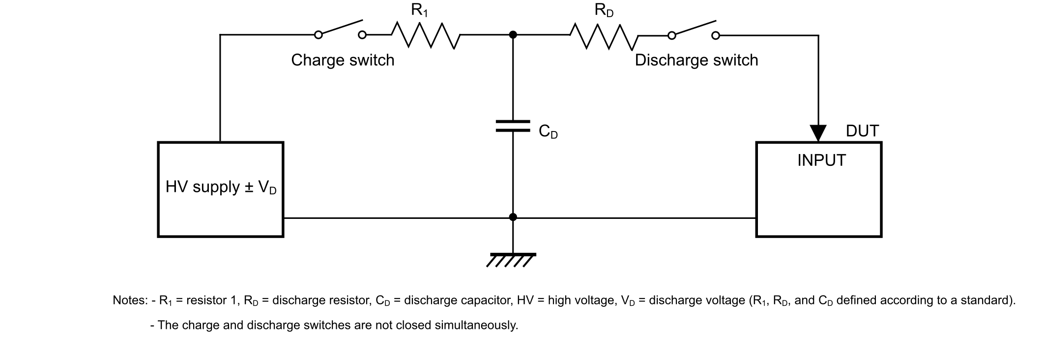
Several models describe how to simulate an ESD stress. The schematic circuit in the figure below shows how to generate an ESD event to a device under test (DUT). It is the basis of these models.

Figure 1. Electrostatic discharge test (ESD generator and DUT)


Human body model (HBM)

An ESD simulator with a special output circuit called the human body model (HBM) is often used to test the susceptibility of electronic devices to ESD stress from human contact. This model simulates the discharge that may occur when a human touches an electronic device (either a system or a component).

The HBM consists of a capacitor in series with a resistor (see Figure 1 Electrostatic discharge test (ESD generator and DUT)). The capacitor is charged to a specified voltage from an external source, and then suddenly discharged through the resistor into an electronic terminal of the DUT.

Machine model (MM)

This model simulates what happens when a machine becomes electrostatically charged and subsequently discharges into an electronic device when it comes in contact with it.

The MM test circuit consists of charging up a 200 pF capacitor to a certain voltage and then discharging this capacitor directly into the DUT.

Standards overview

Some standards exist for the following reasons:
  • to reproduce well-defined tests in terms of setup (bench size, type of isolating area) and conditions (such as temperature and pressure)
  • to eliminate misunderstandings between manufacturers and purchasers
  • to facilitate interchangeability and improvement of products
  • to assist the purchaser in selecting and obtaining the product best suited for its needs

The following subsections provide an overview of the most important ESD standards.

JS-001-2010 international standard

The ESD association and JEDEC solid state technology association have established a joint standard procedure for testing, evaluating, and classifying components and microcircuits according to their susceptibility to damage or degradation by exposure to a defined HBM ESD (1.5 kΩ, 100 pF and 8 kV).

IEC61000-4-2 international standard

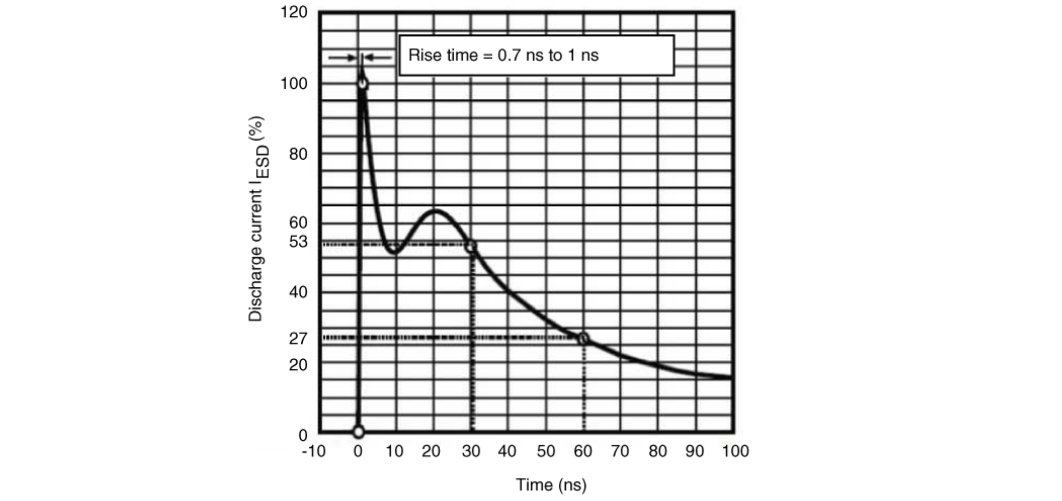
The IEC61000-4-2 standard for ESD protection is ±15 kV for air and ±8 kV for contact. The typical waveform of the output current of the ESD generator is described in the figure below.

Figure 2. IEC61000-4-2 ESD current waveform (RD = 330 Ω, CD = 150 pF)


For this standard, RD and CD of Figure 1 Electrostatic discharge test (ESD generator and DUT) are respectively 330 Ω and 150 pF. This standard is more accurate for performing tests at system level rather than at electronic device level.

MIL-STD-883H

This standard method classifies microcircuits according to their susceptibility to damage or degradation by exposure to ESD. For this standard RD is 1.5 kΩ and CD is 100 pF. This standard is well suited for electronic device tests as ESD stress can be applied directly onto the pins.

ESD standard summary

The application must be aligned with one or more standards as agreed with the customer. Table 2 Test conditions for ESD standards summarizes the test conditions for the ESD standards.

Table 2. Test conditions for ESD standards
StandardModelRD (Ω)CD (pF)±VD (kV)
JS-001-2010HBM1.5 k1008
SP723 EIAJ IC121MM02002

IEC61000-4-2 (level 4)1

HBM and air discharge33015015
HBM and direct discharge3301508
MIL-STD-883H (class 3B) 2HBM1.5 k100≥ 8

When an ESD event occurs, the standards outlined in Standards overview describe four test results that can occur in a real application.

1 Level 4 = maximum level of test voltage in the IEC61000-4-2 standard.
2 Class 3B = maximum level of test voltage in the MIL-STD-883H standard.

Test results of ESD standards

The test results are as follows:

  • normal performance continues within the specification limits
  • temporary degradation or loss of function or performance that is self-recoverable
  • temporary degradation or loss of function or performance which requires operator intervention or system reset (the operator can be the end user)
  • degradation or loss of function that is not recoverable due to damage of equipment (components) or software, or loss of data

The risk of failure is the same for touch sensing application as for other applications. When a touch occurs, the system or equipment can fail if it is not sufficiently robust.