TIM1/8/20 break implementation
The source for break BRK channel is an external source connected to one of the BKIN pins (as per selection done in the AFIO controller), with polarity selection and optional digital filtering.
The source of break2 BRK2 channel is an external source connected to one of the BKIN2 pins (as per selection done in the AFIO controller), with polarity selection and optional digital filtering.
The source for BRK_ACTH (or system break interconnect) is an internal signal coming from:
- The comparator output (on STM32Fx)
- The clock security system
- The lockup of Cortex-M family CPUs
- The PVD output
- The SRAM ECC/parity error signal
- The flash ECC error
BRK
- In all series, the input signal on BRK is connected to the BKIN pin.
- In the STM32F3 series, the input signal on BRK is a logical OR between the input signals on the BKIN pin and the used comparator (4 or 7) output if configured and used internally. If the BKIN alternate function is disabled, the resulting break signal is the comparator (4 or 7) output.
- In the STM32L4 and STM32H7 series (excluding the STM32H7Rx/Sx), the input signal on BRK is a logical OR between the input signals on the BKIN pin, the used comparator (1 or 2) output, and the DFSDM break output if configured and used internally. Each application break source has its own polarity configuration.
- In the STM32U5 series, the input signal on BRK is a logical OR between the comparators (including MDF) break outputs and external sources.
The polarity feature is available for the BRK input. The filter feature is available as well but only on STM32F3/F7/L4/U3/U5/C5 devices.
BRK_ACTH (or system break)
- In the STM32F1/F2/F4/F7 series, this input only gathers the system level fault signals.
- In the STM32F0 series, BRK_ACTH is connected to the system level fault signals and the comparators outputs (1 and 2).
- In the STM32F3 series, BRK_ACTH is connected to the system level fault signals and the comparators (1, 2, 3, 5, and 6).
- For any non-Fx series, the system break request is connected to the system level fault signals.
When this input is used, the polarity selection and filter features are not available. It is always active high.
BRK_ACTH is enabled using the same bit as BRK (BKE in TIMx_BDTR, x= 1, 8, 20).
If there are several system break input sources, the resulting input signal is an OR between all the input signals. Except for the CSS fault signal, the inputs can be individually disabled using the system control block registers.
Other break inputs, external, filter, or comparator are also ORed together and then with the system break inputs. In case of comparator and external signals, polarity must be observed for the logical OR to work as intended.
BRK2
- In the STM32F3 series, this input signal is a logical OR between the input signal on the BKIN2 pin and the used comparators outputs (1, 2, 3, 4, 5, 6, and 7). If the BKIN2 alternate function is disabled (input not used), the resulting break signal is solely related to the comparators.
- In the STM32F7 series, the input signal on BRK2 is connected to the BKIN2 pin.
- In the STM32L4 series, the input signal on BRK2 is a logical OR between the input signals on the BKIN2 pin, the used comparator (1 or 2) output and the DFSDM break output if configured.
- In the STM32U5 series, the input signal on BRK2 is a logical OR between comparators (1 or 2) and MDF1.
- In the STM32L4 and STM32L5 series, it is possible to configure the polarity of each break source in addition except the DFSDM break output to the polarity configuration inside the timer peripheral using BKCMP1P, BKCMP2P, BKINP in TIMx_OR2 register and BK2CMP1P, BK2CMP2P, BK2INP in TIMx_OR3 register.
- In the STM32U5 and STM32H7 series, it is possible to configure the polarity of each break source in addition except the MDF1 (DFSDM) break output to the polarity configuration inside the timer peripheral using BKCMP1P, BKCMP2P, BKINP in the TIMx_AF1 register and BK2CMP1P, BK2CMP2P, BK2INP in the TIMx_AF2 register.
- In the STM32G4 and STM32C5 series, it is possible to configure the polarity of COMP1-4 using BKCMPxPbits in TIMx_AF1 register and BK2CMPxP in TIMx_AF2 register. The rest of the internal inputs have individual polarity fixed to active high, though the collective polarity is still configurable (BKP, BK2P).
- On other series, polarity is individually configurable for all their available COMPx and BKIN/BKIN2 inputs.
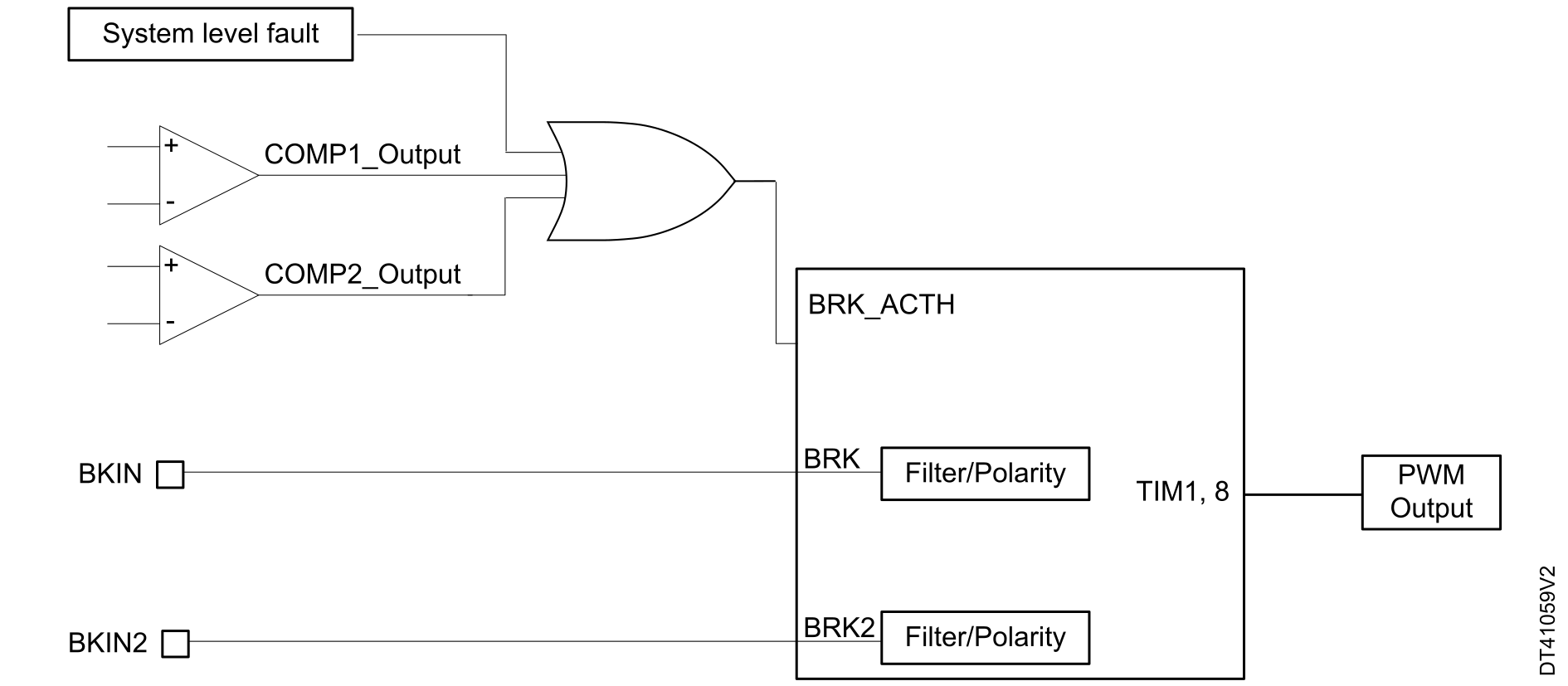
Figure 1 Break feature implementation in advanced timers for STM32F0/F1/F2/F4/F7 series devices shows the break feature implementation for TIM1 and TIM8 in STM32F0/F1/F2/F4/F7 series devices.
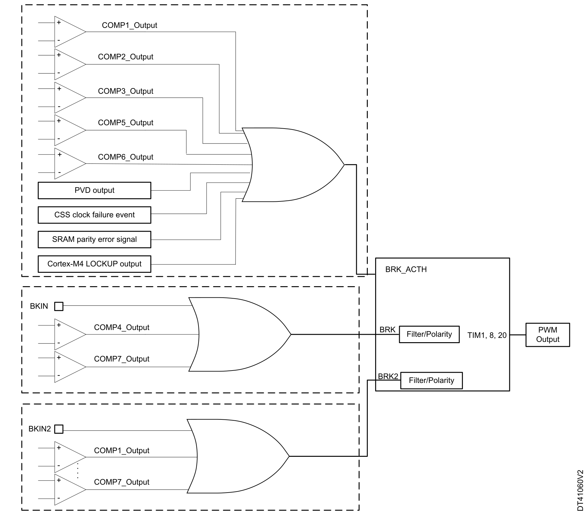
Figure 2 Break feature implementation in advanced timers for STM32F3 series devices shows the break feature implementation for TIM1, TIM8, and TIM20 in STM32F3 series devices.
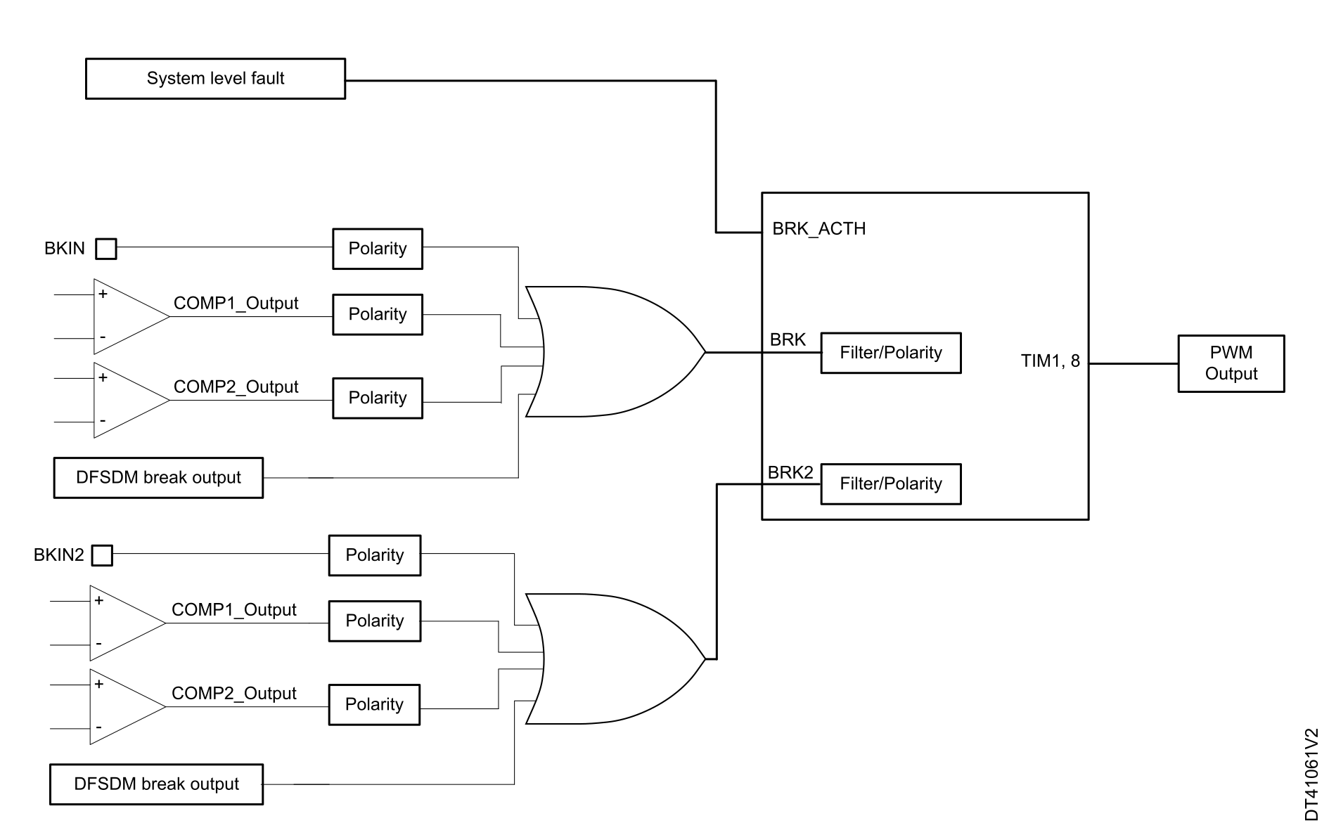
Figure 3 Break feature implementation in advanced timers for STM32L4 series devices shows the break feature implementation for TIM1 and TIM8 in STM32L4 series devices.
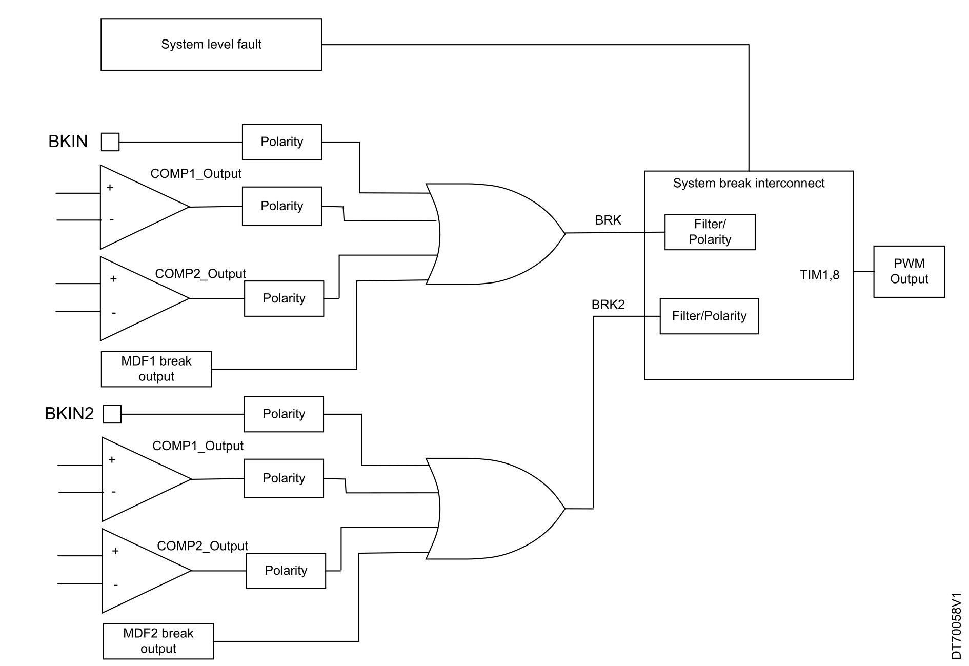
Figure 4 Break feature implementation in advanced timers for STM32U5 series devices shows the break feature implementation for TIM1 and TIM8 in STM32U5 series devices.
Bidirectional break inputs
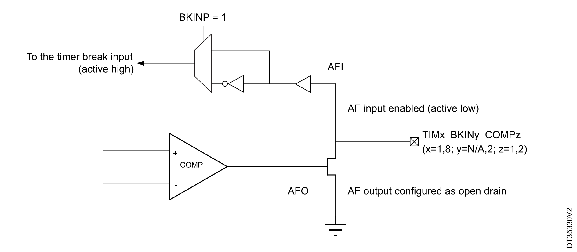
For example in the STM32L4 and STM32U5 series, the timer 1 and timer 8 are featuring bidirectional break input/outputs combining the comparator output (to be configured in open drain) and the Timer BKIN input, as represented in Figure 5 Output redirection.
This feature allows information about the global break available for external MCUs with a single-pin.
TIM15/16/17 break implementation
The source for break BRK channel is an external source connected to one of the BKIN pins (as per selection done in the AFIO controller), with polarity selection and optional digital filtering.
The source for BRK_ACTH is an internal signal coming from:
- The clock security system
- The lockup of Cortex-M family CPUs
- The PVD output
- The SRAM ECC/parity error signal
- The flash ECC error
Inputs from available comparators are ORed with BRK_ACTH signals (on STM32Fx series) or with the external BRK input with polarity selection option.
BRK
- In all series: the input signal on BRK is connected to the BKIN pin.
- In the STM32L4 series: the input signal on BRK is a logical OR between the input signals on the BKIN pin, the used comparator (1 or 2) output and the DFSDM break output if configured.
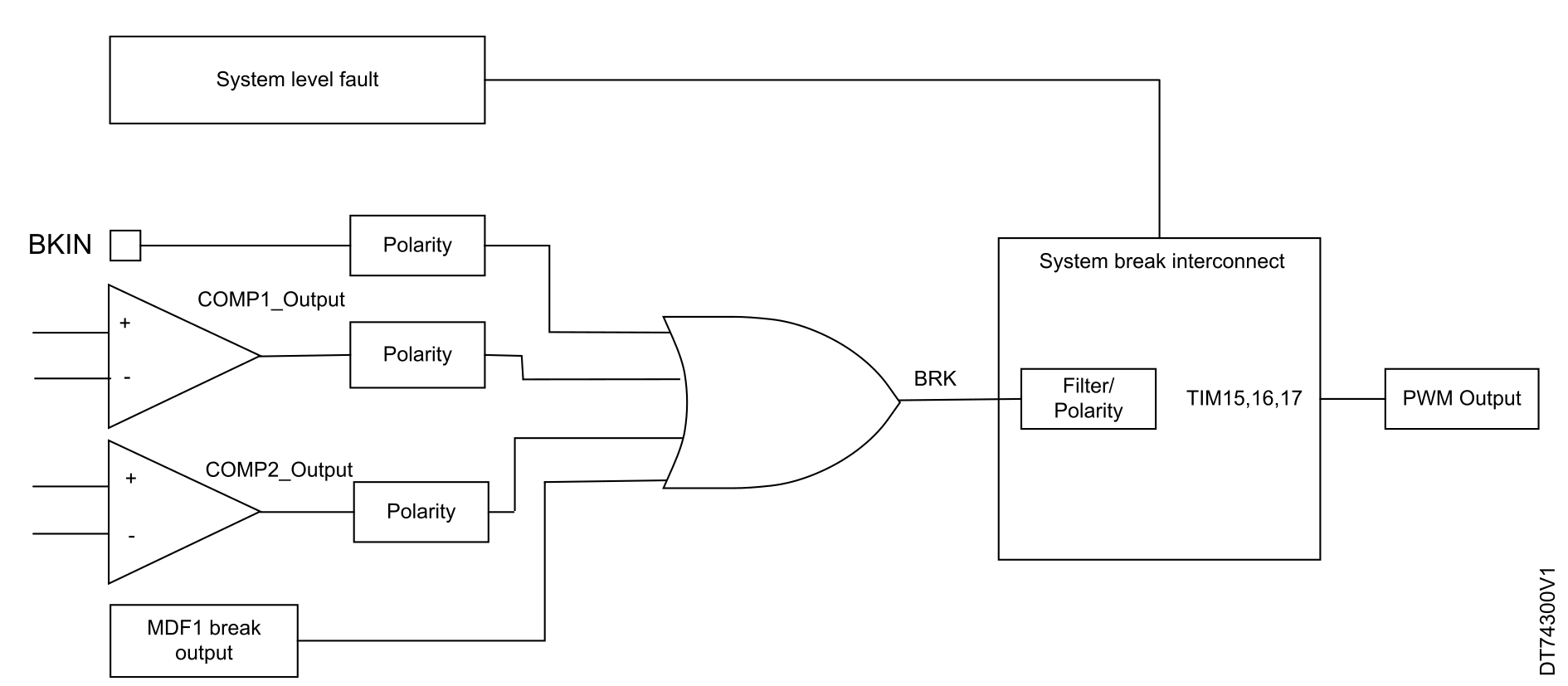
- In STM32U5 series: the input signal on BRK is a logical OR between the BKIN pin, the used comparator (1 or 2) output, and the MDF1 break output.
The polarity selection feature is available for the BRK source.
In STM32L4 series, it is possible to configure the polarity of each break source in addition except the DFSDM break output to the polarity configuration inside the timer peripheral using BKCMP1P, BKCMP2P, BKINP in the TIMx_OR2 register.
In STM32U5 series, it is possible to configure the polarity of each break source in addition. Thus, except the MDF1 break output to the polarity configuration inside the timer peripheral. This is done using BKCMP1P, BKCMP2P, BKINP in the TIMx_AF1 register.
Note: On TIM15-17, the filter feature is only available for STM32C5, STM32Gx, STM32Hx, and STM32U5 devices.
BRK_ACTH (or system break)
- In STM32F1/L4 series, this input only gathers the system level fault signals (CSS, PVD output, SRAM parity error, and the Hardfault).
- In STM32F3 series, BRK_ACTH is connected to the system level fault signals and the comparators (1 and 2) for the STM32F37xxx devices and the comparators outputs (3, 5, and 7) for the rest of the STM32F3 series.
- In other series, system break interconnected sources are CSS, flash, and SRAM ECC errors, PVD and core lockup detection.
When this input is used, the polarity selection and filter features are not available. It is always active high.
BRK_ACTH is enabled using the same bit BRK (BKE in TIMx_BDTR, x= 15, 16, 17).
When using BRK_ACTH as break input, the polarity must be configured high. Otherwise, there is no PWM generation independently of the break signal coming from the internal source.
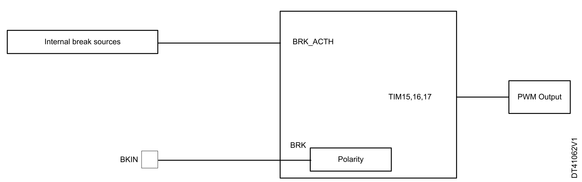
Figure 6 Break feature implementation for TIM15, TIM16, and TIM17 for STM32F1 series devices shows the break feature implementation for TIM15, TIM16, and TIM17 in STM32F1 series devices.
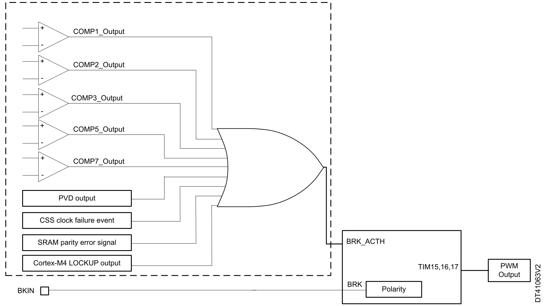
Figure 7 Break feature implementation for TIM15, TIM16, and TIM17 for STM32F3 series devices shows the break feature implementation for TIM15, TIM16, and TIM17 in STM32F3 series devices.
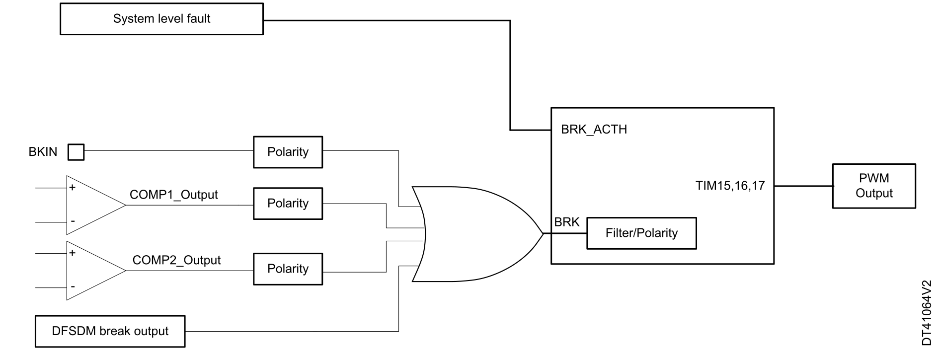
Figure 8 Break feature implementation for TIM15, TIM16, and TIM17 for STM32L4 and STM32H7 series devices shows the break feature implementation for TIM15, TIM16, and TIM17 in STM32L4 series devices.
Figure 9 Break feature implementation for TIM15, TIM16, and TIM17 in STM32U5 series devices shows the break feature implementation for TIM15, TIM16, and TIM17 in STM32U5 series devices.
- If only an internal break source is used, the polarity must be configured to high in the software.
- If there are several break input sources, the resulting input signal is an OR between all the input signals.
- If both internal break source and BKIN are used, the resulting break signal is an OR between the signal pin and the internal break signal.
- If the alternate function AF of the BKIN or BKIN2 pin is not activated, the BRK or the BRK2 is connected to the ground. If the state of the BRK or BRK2 polarity is low, in this case if the break function is enabled, the timer output is disabled. Thus, it must configure the break polarity to high. Only in the STM32F1 series it must configure the break polarity to low.
Note:
STM32G0, STM32H7, STM32WB, and STM32WL are similar to STM32U5, except for MDF.
Break sources summary
Table 4 Break input sources summarizes the available break sources and their connections externally or internally to timers (1, 8, 20, 15, 16, and 17) break inputs.
| - | BRK |
BRK_ACTH | BRK2 |
|---|---|---|---|
| External connection to pin | BKIN | No corresponding I/O | BKIN2 |
| Internal connection to pin |
In STM32F3:
In STM32G4: All comparators, some with polarity control on TIM1/8/20 In STM32L4 and STM32H7(1):
In STM32U5:
|
Available signals from:
|
In STM32F3:
In STM32G4: All comparators, some with polarity control on TIM1/8/20 In STM32L4 and STM32H7(1):
In STM32U5:
|
| Polarity feature in case of internal connection | Configurable for most inputs: active high or active low | Always active high | Configurable for some inputs: active high or active low |
| Polarity feature in case of external break event | Available | NA | Available |
| Filter feature | Not available in STM32F0, STM32F1, STM32F2, and STM32F4. Only available in STM32F3 advanced timers. | NA | Not available in STM32F0, STM32F1, STM32F2, and STM32F4 |
| Available in | TIM1/8/20/15/16/17 | TIM1/8/20/15/16/17 |
TIM1/8/20 in STM32F3, TIM1/8 in other series |
| Resulting break signal in case of parallel external or/and internal break sources | It is an OR between the external break signals and the internal ones. | ||
1 Excluding the STM32H7Rx/Sx line.