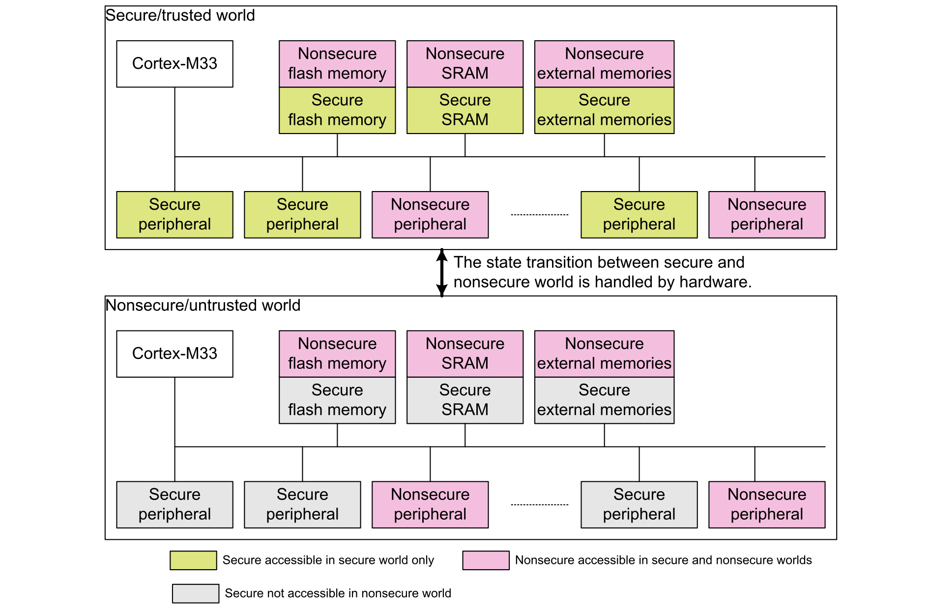
The Arm TrustZone technology for Armv8-M partitions the system into two regions: one is secure world and another is nonsecure world.
The division of secure and nonsecure worlds is memory-map based.
All the available microcontroller resources including flash memory, SRAM, external memories, peripherals and interrupts, are allocated to either the secure or nonsecure world. After planning the security attribution of these resources, nonsecure world only accesses nonsecure memories and resources, while secure world is able to access all memories and resources in both worlds, including secure and nonsecure resources.
Important data that needs protection (such as cryptographic keys) must be placed and processed safely in the secure world .
The location where the code is executed defines its type:
When the code is executed in secure memory, it is called secure code.
When the code is executed in nonsecure memory, it is called nonsecure code.
Secure and nonsecure codes run on the same STM32L5/U5/U3 device, as illustrated in the figure below.Figure 1. Resource partition between secure and nonsecure worlds
Security states
In a simplified view, the executed code address determines the security state of the CPU, that is either secure or nonsecure:
If the CPU runs code in a nonsecure memory, the CPU is in nonsecure state.
If the CPU runs code in a secure memory, the CPU is in secure state.
The Armv8-M technology defines the following address security attributes:
Secure
Secure addresses are used for memory and peripherals that are only accessible by secure code or secure masters. Secure transactions are those that originate from masters operating as secure.
Nonsecure callable (NSC)
NSC is a special type of secure location. This type of memory is the only type for which an Armv8-M processor permits to hold an SG (secure gateway) instruction that enables software to transition from non‑secure to secure state. This SG instruction can be used to prevent nonsecure applications from branching into invalid entry points.
When a nonsecure code calls a function in the secure side:
The first instruction in the API must be an SG instruction.
The SG instruction must be in an NSC region.
Secure code also provides nonsecure callable functions to provide secure service accesses to non‑secure code.
Nonsecure
Nonsecure addresses are used for memories and peripherals accessible by all software running on the device. Nonsecure transactions originate from masters operating as nonsecure or from secure masters accessing a nonsecure address (data transaction only, not fetch instructions). Nonsecure transactions are only permitted to access nonsecure addresses. Nonsecure transactions cannot access to secure addresses.
TrustZone implementation on STM32L5, STM32U5, and STM32U3 series
Activation of STM32L5/U5/U3 TrustZone
In STM32L5/U5/U3 devices, the TrustZone is disabled by default and enabled by setting the TZEN option bit in the corresponding option byte.
All features described in this document apply to the STM32L5/U5/U3 devices with TrustZone enabled.
TrustZone block diagram
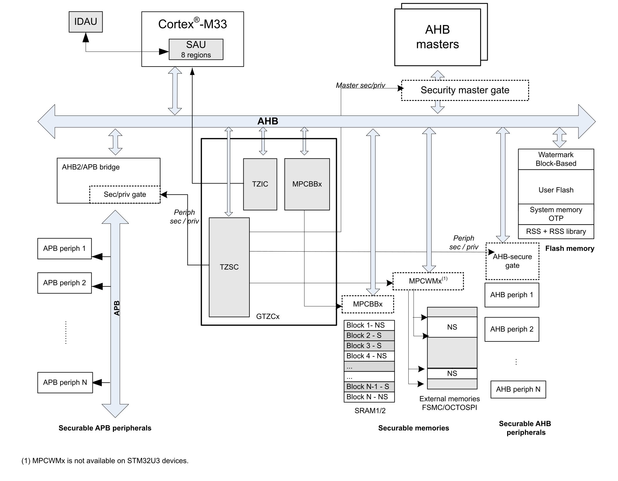
In STM32L5/U5/U3 devices, the TrustZone is implemented thanks to the SAU (secure attribution unit), the IDAU (implementation defined attribution unit), the flash memory, and the GTZC (global TrustZone security controller).
The block diagram below details the TrustZone implementation.Figure 2. STM32L5/U5/U3 TrustZone implementation overview
Secure attribution unit (SAU) and implementation defined attribution unit (IDAU)
The security state of a memory address, seen by the CPU, is controlled by a combination of the internal SAU (secure attribution unit) and the IDAU (implementation defined attribution unit).
The security attribution result is the higher security setting between IDAU and SAU. The priority of security attribution is as follows:
Secure has the highest secure priority.
Nonsecure callable has lower secure priority.
Nonsecure has the lowest secure priority.
The table below shows how to assign a specific security attribute (secure, nonsecure or nonsecure callable) to a specific address.
Table 1. Configuring security attributes with IDAU and SAU
The STM32L5/U5/U3 memory mapping follows the Arm recommendations to implement a duplicated memory map, one for the secure view and the other for the nonsecure view.
This means that each region of the memory map (code, SRAM, peripherals) is divided into two subregions where internal memories and peripherals are decoded at two separate address locations, in the nonsecure view and in the secure view. An IDAU is implemented to define the security attributes of these regions.
The IDAU memory-map partition is not configurable. It is fixed by hardware. The table below shows the memory-map security-attribution partition defined by the STM32L5/U5/U3 IDAU.
Table 2. IDAU memory map address security attribution on STM32L5, STM32U5, and STM32U3
There are eight SAU regions in the STM32L5/U5/U3. The user changes the required security configuration partition by SAU as shown in the table below. When the TrustZone is enabled, the SAU defaults all addresses as secure: all memory regions are considered as secure.
Table 3. SAU memory map address security attribution on STM32L5, STM32U5, and STM32U3
Region
Address range
Security attribute through IDAU
Security attribute through SAU
Final security attribute
Code-external memories when remapped
0x0000 0000 - 0x07FF FFFF
Nonsecure
Secure
Nonsecure or
Nonsecure callable
Secure
Nonsecure or
Nonsecure callable
Code-flash memory and SRAM
0x0800 0000 - 0x0BFF FFFF
Nonsecure
Nonsecure
Nonsecure
0x0C00 0000 - 0x0FFF FFFF
Nonsecure callable
Secure or
Nonsecure callable
Secure or
Nonsecure callable
Code-external memories when remapped
0x1000 0000 - 0x1FFF FFFF
Nonsecure
Nonsecure
Nonsecure
SRAM
0x2000 0000 - 0x2FFF FFFF
Nonsecure
Nonsecure
Nonsecure
0x3000 0000 - 0x3FFF FFFF
Nonsecure callable
Secure or
Nonsecure callable
Secure or
Nonsecure callable
Peripherals
0x4000 0000 - 0x4FFF FFFF
Nonsecure
Nonsecure
Nonsecure
0x5000 0000 - 0x5FFF FFFF
Nonsecure callable
Secure or
Nonsecure callable
Secure or
Nonsecure callable
External memories
0x6000 0000 - 0xDFFF FFFF
Nonsecure
Secure
Nonsecure or
Nonsecure callable
Secure
Nonsecure or
Nonsecure callable
Example
A peripheral is decoded at two address ranges: 0x4000 0000 in nonsecure view and 0x5000 0000 in secure view.
According to the programming of the SAU and IDAU, the secure code accesses the peripheral in the secure view by generating secure transactions, and the nonsecure code accesses the same peripheral at another address in the nonsecure view. The access is either authorized or denied depending on how the peripheral security attribute is defined by GTZC/TZSC. For more details, refer to Security configurations on STM32L5, STM32U5, and STM32U3 series and Overall system security access rules.
SAU configuration in the STM32CubeL5, STM32CubeU5 and STM32CubeU3
The definition of the SAU regions is made in the device partition files located in the following folders:
The secure project enables the SAU and defines the SAU regions. The STM32CubeL5, STM32CubeU5, and STM32CubeU3 define the default SAU regions listed in the table below (associated with linker memory layout file templates).
Table 4. STM32CubeL5 and STM32CubeU5 default SAU regions
All memory space in 0x0000 0000-0xDFFF FFFF not covered by an SAU region is fixed as secure.
The result of the combination between the security attribute provided by the IDAU and the security attribute provided by the SAU, is shown in the tables below.
Table 6. STM32CubeL5 memory security partitioning
Region
Address range
Security attribute through IDAU
Security attribute through SAU
Final security attribute
Flash memory
0x0804 0000 - 0x0807 FFFF
Nonsecure
Nonsecure
Nonsecure
0x0C00 0000 - 0x0C03 DFFF
Nonsecure callable
Secure
Secure
0x0C03 E000 - 0x0C03 FFFF
Nonsecure callable
Nonsecure callable
Nonsecure callable
SRAM1
0x3000 0000 - 0x3001 7FFF
Nonsecure callable
Secure
Secure
0x2001 8000 - 0x2002 FFFF
Nonsecure
Nonsecure
Nonsecure
SRAM2
0x2003 0000 - 0x2003 FFFF
Nonsecure
Nonsecure
Nonsecure
Peripherals
0x4000 0000 - 0x4FFF FFFF
Nonsecure
Nonsecure
Nonsecure
0x5000 0000 - 0x5FFF FFFF
Nonsecure callable
Secure
Secure
External memories
0x6000 0000 - 0x9FFF FFFF
Nonsecure
Nonsecure
Nonsecure
Table 7. STM32CubeU5 memory security partitioningThis table illustrates security partitioning applicable for STM32U575xx/U585xx devices and does not apply to STM32U535xxU545xx, STM32U99xx/U5A9xx, and STM2U5Fxx/U5Gxx devices.
Region
Address range
Security attribute through IDAU
Security attribute through SAU
Final security attribute
Flash memory
0x0810 0000 - 0x081F FFFF
Nonsecure
Nonsecure
Nonsecure
0x0C00 0000 - 0x0C0F DFFF
Nonsecure callable
Secure
Secure
0x0C0F E000 - 0x0C0F FFFF
Nonsecure callable
Nonsecure callable
Nonsecure callable
SRAM1
0x3000 0000 - 0x3002 7FFF
Nonsecure callable
Secure
Secure
SRAM2
0x3003 0000 - 0x3003 FFFF
Nonsecure callable
Secure
Secure
SRAM3
0x2004 0000 - 0x200B FFFF
Nonsecure
Nonsecure
Nonsecure
SRAM4
0x2800 0000-0x2800 3FFF
Nonsecure
Nonsecure
Nonsecure
Peripherals
0x4000 0000 - 0x4FFF FFFF
Nonsecure
Nonsecure
Nonsecure
0x5000 0000 - 0x5FFF FFFF
Nonsecure callable
Secure
Secure
External memories
0x6000 0000 - 0x9FFF FFFF
Nonsecure
Nonsecure
Nonsecure
Table 8. STM32CubeU3 memory security partitioning
Region
Address range
Security attribute through IDAU
Security attribute through SAU
Final security attribute
Flash memory
0x0800 0000 - 0x080F FFFF
Nonsecure
Nonsecure
Nonsecure
0x0C00 0000 - 0x0C07 DFFF
Nonsecure callable
Secure
Secure
0x0C07 E000 - 0x0C0F FFFF
Nonsecure callable
Nonsecure callable
Nonsecure callable
SRAM1
0x3000 0000 - 0x3002 FFFF
Nonsecure callable
Secure
Secure
SRAM2
0x3003 0000 - 0x3003 FFFF
Nonsecure callable
Secure
Secure
Peripherals
0x4000 0000 - 0x4FFF FFFF
Nonsecure
Nonsecure
Nonsecure
0x5000 0000 - 0x5FFF FFFF
Nonsecure callable
Secure
Secure
External memories
0x9000 0000 - 0x9FFF FFFF
Nonsecure
Nonsecure
Nonsecure
This is of course an example. The user must adapt the memory partitioning based on the application requirements in terms of secure and nonsecure resources.