Release Notes for ST Motor Control FW

Copyright © 2022 STMicroelectronics
The STM32Cube is a STMicroelectronics original initiative to ease developers’ life by reducing development efforts, time and cost.
The STM32Cube covers STM32 portfolio.
The STM32 microcontroller offers the performance of the industry-standard Cortex®-M core running either Vector Control or either Field Oriented Control (FOC) modes, widely used in high-performance motor drive for Air Conditioning, Home Appliances, Drones, Building & Industrial Automation, Medical and E-bike applications.
The STM32 Motor Control (MC) Software Development Kit (SDK) includes:
- ST MC FOC FW library;
- ST MC Six-Step FW library
- ST MC Workbench software tool.
The ST MC FOC FW library implements the FOC mode for driving both Internal and Surface Mounted Permanent Magnets Synchronous Motor (PMSM). This implementation can drive one or two motors simultaneously with the characteristics and features listed below.
The ST MC Six-Step FW library implements the Six-Step mode for driving both Internal and Surface Mounted Permanent Magnets Synchronous Motor (PMSM). This implementation can drive one motor with the characteristics and features listed below.
Please, note that some of these features are not supported on all MCUs. In other words, the possible combinations of features and MCUs are discussed below.
Click here to check the supported STM32 microcontrollers and there for the known limitations.
Please, visit us at http://www.st.com to download latest available documents and any update.
The ST MC FOC FW library provides the following features:
Motor Drive
Driving one or two different motors simultaneously (only one for Six-Step)
- In dual motors configuration, any combination of the below-mentioned speed feedback, current sampling, control mode, optional algorithm are allowed
Speed or Torque Control Mode:
- Control Mode can be switched at any time when using FOC (even when the motor is spinning) or at compilation time for the Six-Step;
- Control Mode is set independently for each motor.
Programmable Speed or Torque ramps:
- Ramp duration (FOC only);
- Final target speed or torque.
FOC Loop
SVPWM generation:
- Configurable PWM frequency;
- Centered or Edge PWM pattern type.
Open or Closed Loop operation
- Closed loop is default; However, it is possible to remain in open loop when needed.
Flux Weakening algorithm to reach higher than rated motor speed (optional)
Feed Forward high performance current regulation algorithm (optional)
Maximum Torque Per Ampere (I-PMSM only, optional)
Rev-Up control for sensor less configuration
On-The-Fly startup The sensor less algorithm is able to detect if the motor is already spinning before startup, thus skipping the acceleration phase if needed (useful for fan application)
Real time tuning of:
- PI/PID regulators;
- Sensor less algorithms (Observers, Rev-up procedure);
- Optional algorithms (Feed Forward, Flux Weakening, MTPA…);
- Sensor less startup procedure.
Six-Step Loop
Duty Cycle generation:
- Configurable PWM frequency;
- Centered or Edge PWM pattern type.
Open or Closed Loop operation
- Closed loop is default; However, it is possible to remain in open loop when needed (decided at compilation time)
Startup Control for sensor less configurations
Real time tuning of PID parameters
Back-EMF detection during PWM On time capability
Current Sensing
- Isolated Current Sensing (ICS, FOC only);
- Single Shunt resistor current sensing - common DC-link shunt resistor;
- Three Shunt resistors current sensing - resistors placed on the bottom of the three inverter legs (FOC only);
- In case of dual motors drive setup, current sensing methods can differ from one motor to the other. Then, optimization is possible to share ADCs usage between motors.
FOC Rotor Speed & Position Sensing
- Support for embedded Operational Amplifiers usage on STM32 microcontroller when exists;
- Sensor less Back EMF State Observer coupled with a PLL for rotor speed and angle computation (estimation);
- Sensor less Back EMF State Observer coupled with a CORDIC for rotor speed and angle computation (estimation);
- 60° or 120° displaced HALL sensors decoding (measurement);
- Quadrature Encoder decoding (measurement);
- Two of these above methods can be used simultaneously on any of the motors: Main and Auxiliary one. The Main is used in the control loop, while the other is Auxiliary. Swapping Main with Auxiliary motor are allowed during spinning.
Six-Step Rotor Speed & Position Sensing
- Back-EMF measurement
Motor Brake strategies (FOC only)
- Dissipative DC link brake resistor handling;
- Motor phases short-circuiting (with optional hardware over-current protection disabling);
- Motor phases free-wheeling.
Usage of STM32F30x embedded analog peripherals (FOC only)
Support for Programmable Gain Amplifiers (PGA) usage for current sensing:
- three-shunts and single shunt topologies;
- internal or external gain;
Support for comparators usage in Over-Current Protection (OCP) mode:
- three-shunts and single shunt topologies;
- internal or external threshold;
Support for comparators usage in Over-Voltage Protection (OVP) mode:
- motor phases short-circuiting mode and free-wheeling mode;
- internal or external threshold.
Usage of FOC specific STM32F30x hardware accelerations (FOC only)
- ADC queue of context (ST patented architecture);
- CCM (core coupled memory) RAM;
- Advanced Timer structures for single shunt topology (ST patented).
Fault Management
- Over-Current;
- Over-Voltage
- Under-Voltage;
- Over-Heating;
- Speed feedback reliability error (FOC only);
- FOC algorithm execution overrun.
Supported devices and boards
Supported Devices:
- STM32F0xx Family: STM32F030RC / STM32F030R8 / STM32F031C6 / STM32F051R8 / STM32F051C8 / STM32F072VB / STM32F072RB
- STSPIN32 Family: STSPIN32F0601 / STSPIN32F0602 / STSPIN32F0251 / STSPIN32F0252 / STSPIN32F0A / STSPIN32F0B / STSPIN32G4
- STM32F1xx Family: STM32F103 High, Medium and Low Densities
- STM32F3xx Family: STM32F302VB / STM32F302VC / STM32F302R8 / STM32F303VB / STM32F303VC / STM32F303ZE / STM32F303VE / STM32F303RE
- STM32F4xx Family: STM32F417IG / STM32F415ZG / STM32F407IG / STM32F446ZE / STM32F446RE / STM32F401RE
- STM32F7xx Family: STM32F746ZG / STM32F769NI
- STM32L4xx Family: STM32L452RE / STM32L476RG
- STM32G0xx Family: STM32G081
- STM32G4xx Family: STM32G431CB / STM32G431RB / STM32G474QE
- STM32H7xx Family: partially supported with examples STM32H745ZI
Control Boards
STM32F0xxFamily:
- NUCLEO-F030R8
- NUCLEO-F072RB
- STM32072B-EVAL
STM32F1xx Family :
- NUCLEO-F103RB
- STM3210E-Eval
STM32F3xx Family:
- NUCLEO-F302R8
- NUCLEO-F303RE/NUCLEO-F303RB
- STM32303E-EVAL
STM32F4xx Family:
- NUCLEO-F446RE
- NUCLEO-F401RE
- STM3240G-EVAL
- STM3241G-EVAL
- STM32446E-EVAL
- STEVAL-IHM039V1
STM32F7xx Family:
- NUCLEO-F746ZG
- STM32F769I-EVAL
STM32L4xx Family:
- NUCLEO-L452RE
- NUCLEO-L476RG
- STM32L476G-EVAL
STM32G0xx Family:
- STM32G081B-EVAL
STM32G4xx Family:
- NUCLEO-G431RB
- STM32G474E-EVAL
STM32H7xx Family:
- NUCLEO-H745ZI-Q
Power Boards:
- STEVAL-IHM023V3
- STEVAL-IHM025V1
- STEVAL-IHM028V2
- STEVAL-IHM045V1
- STEVAL-IPM05F
- STEVAL-IPM07F
- STEVAL-IPM08B
- STEVAL-IPM10B
- STEVAL-IPMM10B
- STEVAL-IPM10F
- STEVAL-IPM15B
- STEVAL-IPMM15B
- STEVAL-IPM20B
- STEVAL-IPM30B
- STEVAL-IPMNG3Q
- STEVAL-IPMNG3S
- STEVAL-IPMnM3Q
- STEVAL-IPMNG5Q
- STEVAL-IPMnM5Q
- STEVAL-IPMNG8Q
- STEVAL-IPMNM1N
- STEVAL-IPMNM2N
- STEVAL-IPMNM1S
- STEVAL-CTM009V1
- X-NUCLEO-IHM07M1
- X-NUCLEO-IHM08M1
- X-NUCLEO-IHM11M1
- X-NUCLEO-IHM16M1
- EVALSTDRIVE101
Inverter Boards
- STEVAL-IHM034V2 (STM32F1)
- STEVAL-IHM042V1
- STEVAL-SPIN3201
- STEVAL-SPIN3202
- X-NUCLEO-IHM16 + NUCLEO-F303RE bundle
- STEVAL-ESC001V1
- B-G431B-ESC1
- EVSPIN32F0601S1
- EVSPIN32F0601S3
- EVSPIN32F0251S1
- EVSPIN32F0602S1
- STEVAL-HKI001V2
- STEVAL-CTM010V1
Known Limitations
LCD screen on EVAL boards are not supported;
Ac6 System Workbench for STM32 (SW4STM32) toolchain is not supported.
With STM32CubeMx 5.0.0:
- Motor Control Projects configurations using an STM32L4 device do not work if generated using the LL drivers. Using the HAL ones is OK.
- Motor Control Projects configurations using an STM32L4 device fail to generate if ADC discontinuous mode is set while scan mode is disabled. This is typically the case for projects using ICS as the current sensing technology.
With STM32CubeMx 5.0.1:
- Motor Control Projects configurations using an STM32L4 with ICS as current sensing topology do not work.
With STM32CubeMx 5.2.0:
- Configurations based on STM32G4xxx using a Single-Shunt current sensing topology and initializing the peripherals with the LL drivers cannot be generated.
- Generating ADC initialization with the LL drivers on STM32G4xxx or STM32L4xxx based configurations results in a non working code.
- Generating TIMers initializations with the LL drivers on STM32G4xxx based configurations results in a non working code.
With STM32CubeMx versions 5.5.0, 5.6.0 and 5.6.1:
- Generating ADC initialization with the LL drivers on STM32F4xx and STM32F7xx based configurations results in a non working code. Indeed, for these series, ADC injected channels configuration code generation is broken with the LL drivers.
The example provided for the NUCLEO-H745ZI control board now requires ST32CubeMx version 5.6.0 or later to be generated properly.
With STM32CubeMx 6.2.0:
- MC Workbench reports an error when generating projects for STM32G0xx devices with STM32CubeMx 6.2.0. This error actually is a warning from STM32CubeMx that does not prevent a correct generation of the project. Generated projects are functional.
X-CUBE-MCSDK version 5.Y.0 does not support dual drive configurations.
Overmodulation is not working with STM32F0 family when running is negative speed.
With STM32CubeMx 6.4.0:
- Peripheral initialization code generation for STM32G0xx series with LL drivers has a limitation that causes variations of the rotation speed and sometimes “startup failure” errors.
A SW workaround is available. It consists in calling function
LL_RCC_SetTIMClockSource(LL_RCC_TIM1_CLKSOURCE_PLL)just after the call toMX_TIM1_Init()in themain()function in filemain.c.
- Peripheral initialization code generation for STM32G0xx series with LL drivers has a limitation that causes variations of the rotation speed and sometimes “startup failure” errors.
A SW workaround is available. It consists in calling function
Update History
V5.Y.4 / 18-January-2022
Main Changes
Version 5.Y.4 of the Motor Control Software Development Kit (X-CUBE-MCDSK) is a bug fix release of version 5.Y.3. Its main purpose is to add support of STM32CubeMx version 6.4.0.
In addition, it also provides the following new features:
The state machine that controls overall motor operation has been redesigned and simplified. See New Motor Control state machine
MISRAC-2012 compliance. The SDK can produce software projects which sources are compliant with MISRAC-2012 recommendations. This feature is available for Motor Control applications running on STM32G4 MCUs. See Activating MISRA compliance below.
Added a CPU load measurement mechanism. Thanks to this mechanism, the CPU consumption of the High and the Medium Frequency tasks is measured. Results can be retrieved through the Motor Pilot. See CPU load measurement feature below.
Changed the names of some example files to ensure that they are unique (no STMCX example file has the same name as another one in the release).
Added floating point API to the Motor Control API. For most of the functions of the Motor Control API that take numeric parameters as input and/or return a numeric parameters, another function is added that take and/or return float type parameters and values. This is the case for all functions whose numerical parameters represent physical quantities. the unit of the float parameters are the natural physical units: Amperes for currents and torques, Volts for voltages, seconds for time... See the Motor Control API module of the Motor Control SDK Reference Manuel for a complete information.
Added an API for getting the average measured motor power, in Watts:
int16_t MPM_GetAvrgElPowerMotor*(void)(andfloat MC_GetAveragePowerMotor1_F(void)for its float version). See the Motor Control API module of the Motor Control SDK Reference Manuel for a complete information.Added a APIs for getting information from auxiliary speed and position feedback components:
int16_t MC_GetMecAuxiliarySpeedAverageMotor*(void)andfloat MC_GetMecAuxiliarySpeedAverageMotor*_F(void);int16_t MC_GetAuxiliaryElAngledppMotor*(void)andint16_t MC_GetAuxiliaryElAngledppMotor*(void).
See the Motor Control API module of the Motor Control SDK Reference Manuel for a complete information.
Removed the Encoder Align APIs from the Motor Control API (
MC_AlignEncoderMotor*(void)). These API are not useful since an alignment is performed if needed onMC_StartMotor*()invocation.Added an Offset Measurement (aka Polarization Measurement) API procedure and its APIs. This procedure measures the offsets of the current measurement network (the voltage sampled on the ADC when no current is flowing into the motor) so that they can be stored (e.g. in a non volatile memory) and be reused later. This allows for shortening the boot-to-spin time as it removes the need to measure these offsets at each power on. The API provided with the procedure allows for:
- triggering the Offset Measurement procedure that will measure the offsets:
bool MC_StartPolarizationOffsetsMeasurementMotor*( PolarizationOffsets_t * PolarizationOffsets ); - getting measured offsets:
bool MC_GetPolarizationOffsetsMotor*( PolarizationOffsets_t * PolarizationOffsets ); - setting already measured offsets:
bool MC_SetPolarizationOffsetsMotor*( PolarizationOffsets_t * PolarizationOffsets ).
The use of this procedure is optional. On a call to
MC_StartMotor*(), this procedure is triggered automatically if no offset has been provided before.- triggering the Offset Measurement procedure that will measure the offsets:
Enabled the use of the On The Fly feature with configurations that use Hall sensor as their Speed and Position feedback technique.
Release 5.Y.4 also fixes the following issues found in earlier versions of the SDK:
- Fixed the
FF_GetVqdAvPIout()function that now returns instead of . - Fixed a naming issue between UART and USART peripherals that could result in compilation issues.
- There was a compilation failure with the Position control example. This is now fixed.
- Fixed a Hard Fault that would occur in Single Shunt + Overmodulation configurations.
- The priority of the Systick interrupt was not set correctly. This is now fixed.
- The square root function of the CORDIC IP was sometimes yielding wrong results because of a configuration issue. This is now fixed.
- A division by 0 situation could occur when symbol
OPEN_LOOP_FOCwas defined. This is now fixed. - Fixed an issue that prevented from building 6-Step sensor-less examples on STM32F0 based MCUs.
- Fixed an over current issue that would occur in Single shunt + Hall sensor configurations.
- Fixed an issue with the use of CCMRAM in configurations using a State Observer +Cordic for speed and position feedback and built with the GNU C compiler (STM32CubeIDE).
- Fixed a build issue impacting 6 Step examples with
FAST_DEMAGon STM32F3 and STM32G4 MCUs. - Fixed an issue that preventing STM32F3 based projects using 2 ADCs and internal OpAmps for current sensing from building.
- Fixed a Hard Fault that would occur when sending an "Execute Set Position" command from the Motor Pilot to a Position Control application built with the GNU C compiler (STM32CubeIDE).
- Fixed an issue with configurations using a State Observer + PLL for speed and position feedback, where a speed feedback error could be unduly reported when both speed and speed variance are high.
- Fixed an issue with the charging of the bootstrap capacitor.
New Motor Control state machine
The state machine used in earlier versions of the SDK had several issues. Among others, it was more complex than actually needed and its implementation was letting the door open to missing state transitions. More especially, fault conditions and commands could be missed in some very specific (and very rare) conditions.
The new state machine aims at solving these issues. One of the most visible improvement is its simplification as it goes from 21 to 12 states. The following figure provides an overview of this new state machine.

The new state machine will be documented in details in further versions of the SDK.
Activating MISRA compliance
MISRAC-2012 compliance brings an additional cost in RAM, FLASH and MIPS consumption. This is why this feature is disabled by default.
To enable it globally, define symbols FULL_MISRA_C_COMPLIANCY and NULL_PTR_CHECK at project level. The second symbol enables the checking of pointers passed as parameters to many the functions of the SDK. The first one enables the replacement of right shifts operations with divisions by powers of two. Null pointer checking activation can be enabled and disabled independently of the rest of MISRA compliance code because of its important impact on the performances.
The MISRA compliance feature can be activated either as a whole or on a per component basis thanks to two sets of defines (one for null pointer checks and one for the rest of MISRA code) named after the component they relate to. These symbols are defined in the mc_stm_type.h file. Refer to this file for more information.
The MISRA compliance feature is only available for STM32G4 MCUs.
CPU load measurement feature
This mechanism is activated at project generation time. Activation of the feature is not supported by the Workbench yet. So, to activate it, load the project IOC generated by the Workbench in STM32CubeMx, navigate to the Middleware, MotorControl panel and check the DBG_MCU_LOAD_MEASURE box. Then, click the "GENERATE CODE" button. See the Parameters visibility in STM32CubeMx section below for detailed information on parameters in STM32CubeMx.
To retrieve the measurements, three registers of the Motor Control Protocol are provided. The Motor Pilot can be used to get and to plot them:
PERF_CPU_LOAD: its value reflects the latest CPU load measurement available;PERF_MIN_CPU_LOAD: set to the minimum CPU load measured in the session;PERF_MAX_CPU_LOAD: set to the maximum CPU load measured in the session.
The performance measurement counts the cumulative number of processor cycles spent in the High and Medium frequency tasks during a Medium Frequency Task period (typically 1 ms, see the Execution rate parameter of the Speed regulator panel in the Workbench). The values of the registers represent the ratio between the measured number of cycles and the total number of cycles in a period, expressed in percent.
Note that Min & Max value represent the absolute values measured during regular execution time. These values are not updated during the calibration phase.
The plotting of these registers is done with the polling method (and not using the Datalog service). So, the value plot of register PERF_CPU_LOAD in the GUI is a subsampling of the MCU load value.
STM32Cube Environment
- STM32CubeMX v6.4.0
- STM32Cube_FW_F0_V1.11.3
- STM32Cube_FW_F3_V1.11.3
- STM32Cube_FW_F4_V1.26.2
- STM32Cube_FW_F7_V1.16.1
- STM32Cube_FW_G0_V1.5.0
- STM32Cube_FW_G4_V1.5.0
- STM32Cube_FW_L4_V1.17.0
- STM32Cube_FW_H7_V1.9.0
Development Toolchains
- IAR Embedded Workbench for ARM (IAR Systems AB) v8.4.
- μVision® IDE for Arm® (Keil® MDK) v5.24.2
- STM32CubeIDE v1.6.1
- STM32CubeProgrammer 2.6.0
V5.Y.3 / 14-Sep-2021
Main Changes
Version 5.Y.3 of the Motor Control Software Development Kit (X-CUBE-MCDSK) is a bug fix release of version 5.Y.2.
It fixes the following issues:
- Reintroduced pdf documentations that had disappeared in 5.Y.2.
V5.Y.2 / 22-July-2021
Main Changes
Version 5.Y.2 of the Motor Control Software Development Kit (X-CUBE-MCDSK) is a bug fix release for supporting STM32CubeMX version 6.3.0. In addition, it provides a few other updates and improvements on top of 5.Y.1:
Fixed a build issue that would occur when using a resistive brake in a motor control configuration
Changed the visibility of some Six Step parameters in STM32CubeMx. See Parameters visibility in STM32CubeMx below for detailed information.
Fixed an issue that prevented a master to connect to the Motor Control application with the Motor Control Protocol when its capabilities are smaller than that of the slave.
Datalog buffers are immediately sent when an error occurs, even if incomplete. This allows the user for getting the latest values of monitored signals when the error occurs.
Kp/Ki dividers values are now aligned and provided as a power of 2 (Set/Get APIs updated).
New 6Step example project provided for supporting STEVAL-PTOOL1V1 board.
Parameters visibility in STM32CubeMx
The Six Step drive firmware currently delivered with the SDK is not configurable with the Motor Control Workbench yet and it is only available through examples. However, the user can have some level of control over the configuration of the examples thanks to STM32CubeMx. Loading the .IOC file produced by the workbench into STM32CubeMx, navigating to the Pinout & Configuration pane, Component List (Categories) column, MiddleWare section and then clicking on MotorControl displays a configuration panel (See below).
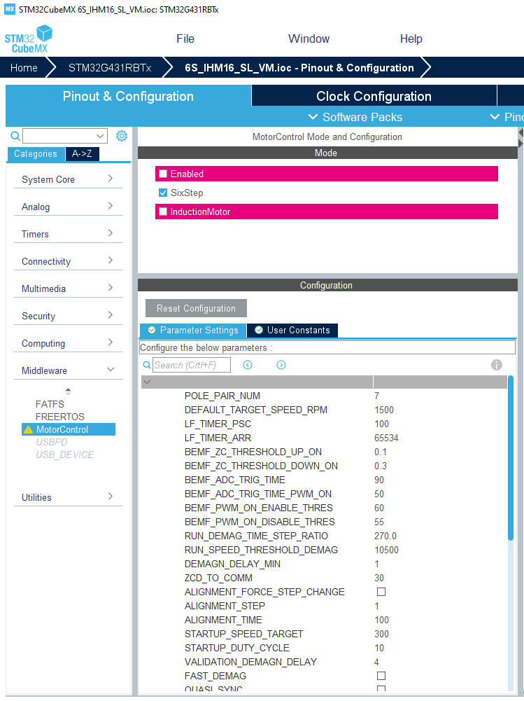
This panel appears on the right of the Component list column and displays a subset of the parameters of the Motor Control firmware. Refer to the documentation for the meaning of these parameters and how to change them. Most of these parameters belong to the Six Step drive firmware while some are shared with the FOC drive. Among the latter, ASPEP_OVER_UART and those which name starts with MCP_ configure the remote communication with the application with Motor Control Protocol. Users should not change them from STM32CubeMx unless they know the consequences.
Note that parameters shared with FOC drive are also displayed in STM32CubeMx in FOC configurations. However in this context, they must not be changed from STM32CubeMx. Indeed, some other, non visible, but related parameters may not be updated accordingly and changes made in the IOC file are not propagated back to the .STMCX MC Workbench project file.
V5.Y.1 / 3-May-2021
Main Changes
Version 5.Y.1 of the Motor Control Software Development Kit (X-CUBE-MCDSK) is a bug fix release of version 5.Y.0.
It fixes the following issues:
- Some Motor Control examples delivered with MCSDK 5.Y.0 would not configure DMA channels properly to work with the new Motor Control and thus with the Motor Pilot. Also, the baudrate of the UART port configured by examples is set to 1,8 Mbps, the same as ST Motor Pilot's default.
- ACIM motor based examples do not build on 5.Y.0. They build well on 5.Y.1.
- Six-Step High Voltage examples based on the EVSPIN32F0251S1 inverter board were mistakenly not included into 5.Y.0 version. They are in 5.Y.1.
- Added many signals to the Datalog and the DAC output features. Among them, the observers, encoder and Hall sensors angles.
- Running the motor in the negative direction on STM32F0 based designs with 1 shunt and Hall sensor configuration may trigger an overcurrent error.
- Fixed an issue found on ESC G4 and F3 inverter boards with Motor Control Protocol v2.
V5.Y.0 / 23-Apr-2021
The release 5.Y.0 of the Motor Control Software Development Kit (X-CUBE-MCDSK) is a step in between the current legacy version (v5.4.6 ) and the coming Version 6.
X-CUBE-MCSDK version 6 will allow:
- A better and broader integration within the STM32 ecosystem of devices and tools with out of the box support for more STM32 devices and deeper collaboration with STM32CubeMx;
- A renewed Motor Control SDK configuration tool. The workbench needs a major overhaul in order to properly cope with the many new Motor Control features that are pending integration into the SDK. Although the new Workbench is not yet available, some of these "new Motor Control features" are included in the 5.Y.0 version;
- A new and powerful debug tool. ST Motor Pilot is a new control and monitoring PC tool that will replace the Monitor currently delivered with the Workbench. It is built on a brand new communication protocol that allows for faster and more reliable communication while consuming less MIPS from the MCU. With this protocol, internal Motor Control signals can be monitored in real time with no or controlled subsampling.
- Also, the support for STM32F1 series is dropped from MCSDK 6 versions line.
Main Changes
In version 5.Y.0, the following changes are introduced:
- A brand new communication protocol has been implemented and replace the legacy version. Motor Control Protocol version 2 over U(S)ART with high Baud rates (up to 1.8 Mbps for the time being for STM32G4 series)
For PMSM/BLDC Motors:
Discontinuous PWM (aka. Two-phase modulation)
- DPWM can be activated from the Workbench, in the Firmware Drive Management / Additional Features tab
Over Modulation
- Over Modulation can be activated from the Workbench, in the Firmware Drive Management / Additional Features tab
Single Shunt with Phase Shift. This variant of the Single Shunt current sensing topology replaces the active window variant that used to be delivered with the SDK
Circle Limitation VD, a better variant of the circle limitation algorithm where that
Vdis never 0 which prevents some uncontrollable situations. It replaces the legacy implementationAdded support for the STSPIN32G4 devices
Removed support for the STM32F1 devices series.
For Asynchronous Motors:
- ACIM motors are supported as two examples featuring FOC sensorless and V/f (scalar) modes. A graphical PC tool is delivered wit the SDK to help configuring this example: ACIM GUI. The two examples are designed for NUCLEO-G431RB + STEVAL-IHM023V3 configurations.
IMPORTANT WARNINGS
- STM32F1 Family is not supported by X-CUBE-MCSDK version 5.Y. If you are using a STM32F1 MCU, please keep on using X-CUBE-MCSDK 5.4.x versions.
- Dual Drive is not supported by current X-CUBE-MCSDK version 5.Y. If you are using dual drive, please keep on using X-CUBE-MCSDK 5.4.x versions.
- Projects generated with previous X-CUBE-MCSDK versions will not load with the version 5.Y. Please stay with versions 5.4.x if you want to keep the compatibility.
- X-CUBE-MCSDK version 5.Y is released to provides users with an insight on the directions that the development of the Motor Control SDK is following but is not aiming to reach the same level of maturity of legacy X-CUBE-MCSDK version 5.4.6
V5.4.6 / 15-Mar-2021
Main Changes
Version 5.4.6 is a bug fix release of X-Cube-MCSDK v5.4.5.
- Added support for STM32CubeMx version 6.2.0: updated the B-G431-ESC1 example to take into account the changes introduced by this version of STM32CubeMx;
- Fixed an error in the Release notes of version 5.4.5 of the SDK about the usage of Injected ADC conversions on STM32G4 devices. The corrected paragraph is readable in place, here;
- Fixed a typo in the Release notes about the name of an inverter board: EVSPIN32F0601S1 was incorrectly named STSPIN32F0601S1.
Note: This bug fix release of X-Cube-MCSDK still supports IARM EWARM 7.x. See the V5.4.5 release section and IAR EWARM 7.x end of support paragraph below
V5.4.5 / 18-Dec-2020
Main Changes
Version 5.4.4 is mainly a bug fix release of X-Cube-MCSDK v5.4.4. It also introduces a few new features.
End of support of IAR EWARM 7.x for the Web release variant. Binary libraries delivered with the Web variant of MCSDK, for the IAR EWARM toolchain, were built with IAR EWARM version 7.80 in previous releases. Starting with MCSDK 5.4.5, they are built with IAR EWARM version 8.20. MCSDK 5.4.5 still provides binary libraries built with IAR EWAM 7.80, though. See section... for more details. Note that future MCSDK releases will not provide libraries for IAR EWARM 7 anymore.
Added support for the following power boards:
- STEVAL-IPMM10B
- STEVAL-IPMM15B
- STEVAL-IPM20B
- STEVAL-IPM30B
- STEVAL-IPMnM3Q
- STEVAL-IPMnM5Q
Added support for STM32G4 Cut 2.2: the firmware and some of the G4 examples in delivery 5.4.4 would not work when used with STM32G4 Cut 2.2. They have been updated to support this cut of the STM32G4 devices.
Fixed an issue with the overcurrent error due to the overflow or underflow of CCR registers of the PWM Timer not being checked.
Fixed an issue with ICL activation/deactivation
Fixed an issue with regular ADC conversions on STM32G4 when the sampling time is high.
Fixed an issue with the G4 CCMRAM example where some function were not placed in CCMRAM while they should have been.
Fixed an issue with On The Fly startup feature when the motor is already spinning beyond the closing loop threshold, in the direction opposite to the requested startup speed.
IAR EWARM 7.x end of support
This section is meaningful for the web variant of the MCSDK only. The Full variant of MCSDK is not impacted since it is not delivered with binary libraries.
Binary libraries built with version 7.x of IAR EWARM can be used to generate MCSDK projects that build with IAR EWARM 7.x and 8.x. However, when used in EWARM 8.x projects, warnings are generated due to different sizes of the wchar_t type between EWARM 7.x and 8.x. These warnings are a source of frequent problem reports though they do not have negative consequences. In addition, EWARM 8.x has been available for a few years now. So, it is time now to definitively switch to EWARM 8.x and drop support for EWARM 7.x.
Starting with the next release of MCSDK, Web variant binary libraries will be built with EWAM 8.x. This will make it impossible to build with EWARM 7.x and older.
For the present release, Web variant binary libraries are provided both for EWARM 7.x and EWARM 8.x. However, when generating a project for IAR EWARM, only EWARM 8.x libraries are pulled in the project even if EWARM 7.x was selected in the workbench. To use the EWARM 7.x libraries the following procedure can be used:
- Remove the EWARM 8.x library from the generated project. It is located in the
MCSDK_v5.4.5/MotorControl/libfolder in the generated project and namedlibmc-iar_M*.a, withM*the name of the Cortex M core used by the STM32 in the project. The folder contains all the libraries for all the cores and toolchains. Only one of them is actually used and its name is listed in the EWARM project. - Copy the EWARM 7.x library file needed for the project from the
Middlewares/ST/MotorControl/libfolder found in the MCSDK installation location. In this folder, EWARM v7.x libraries are namedlibmc-iar7_M*.a. - Rename the
libmc-iar7_M*.afile intolibmc-iar_M*.a.
V5.4.4 / 19-May-2020
Main Changes
Version 5.4.4 is mostly a bug fix release of X-Cube-MCSDK v5.4.3. It also introduces some new feature.
- Added Support for PFC on STM32F3. This support is added as an example for the STEVAL-CTM010V1 Dual motor demo board.
- Atollic TrueSTUDIO & SW4STM32 Deprecation. Atollic TrueSTUDIO and SW4STM32 IDEs are no longer actively developed and ST's strategy is to replace them with STM32CubeIDE. Recent STM32 series like STM32G4 devices for instance, are already not supported by all these IDEs. In a near future release of the Motor Control SDK, support for these IDE will be dropped and it will not be possible anymore to generate a project for them from the Workbench.
- Introduced a workaround for the issue with injected ADC conversions that exists on STM32G4xx Cut 2.2 devices. See the dedicated section below for more details.
- Reintroduced the correct ST Motor Profiler version (the same as release 5.4.1 of the SDK). The Motor Profiler delivered with MCSDK 5.4.2 and 5.4.3 was incomplete.
- Fixed an issue with the faulty setting of the maximum application current for the second drive in dual drive configurations
- Fixed an issue with Position Control configurations using an absolute position encoder (with Z signal).
- Fixed another issue with Position Control where a division by 0 was possible.
- Fixed a bootstrap capacitor charge issue in ICS configurations
- Fixed a SW Error that could occur during the offset measurement loop
- Fixed a code generation issue resulting in a compilation error when enabling open loop.
- Fixed a STM32H7 example compilation issue - missing files have been added.
- Fixed a generation issue for some STM32G0 and STM32F0 devices where TIM2 does not exist but was referenced in the code anyway. This resulted in a compilation failure.
- Fixed an issue with STM32F1 HD devices in single shunt configurations
The Release Note will be modified as follows:
Injected ADC conversions issue on Cut 2.2 of STM32G4xx devices
If injected conversions are interrupting a set of scan conversions (scan group) then the first conversion from this injected group is always zero and the other conversions of this injected group are correct. This issue is found on the Cut 2.2 of STM32G4xx devices.
The Motor Control SDK uses Injected ADC conversions to perform current measurements where they are available. This includes the devices of the G4 series.
The workaround introduced in this release of the MCSDK consists in triggering one of the regular conversions scheduled for other needs right after the injected ones used for current measurement. This guarantees the injected conversions will not interrupt the regular ones. This strategy is the one used for STM32F0 and STM32G0 devices that do not have the injected conversion feature.
V5.4.3 / 18-Nov-2019
Main Changes
- Fixed STSPIN based 6-Step examples that failed to build due to API changes in the HAL drivers.
- Fixed issues with accessing Position Control specific Motor Control Protocol registers
- Fixed complex examples for STM32G4 that missed the required activation of the CORDIC HW IP
Using STM32CubeIDE with the Motor Control SDK
It is now possible to generate Motor Control application projects for STM32CubeIDE. These projects come with two build configuration, Release and Debug.
The Release configuration builds the application with the highest level of optimization, geared towards speed (-Ofast) but does not provide any debug capability. This configuration is meant for production firmware.
The Debug configuration, on the contrary, will provide the highest level of debug capability (-g3) but no optimization (-O0). Unfortunately, this configuration may not work out of the box with Motor Control Application:
- The absence of any optimization may result in a binary that is too large to fit in the target MCU. When this occurs, the build fails at the link step;
- Without any optimization, it is very likely that the application will emit a "FOC duration" fault immediately when the motor is started.
To be able to debug the application, the Debugbuild configuration needs to be modified to add optimization. This can be done in the Project properties dialog, section C/C++ Build, selecting the Debug configuration and selecting Optimize for Speed for the MCU GCC Compiler / Optimization item.
V5.4.2 / 04-Nov-2019
Main Changes
Added support for the following features to configurations based on STM32G4xx devices:
- The embedded CORDIC math coprocessor;
- Insulated Current Sensing;
- Dual motors drive
Introduction of the Position Control feature for configurations using a Quadrature Encoder as speed and position feedback. See the section Using the Position Control feature below for more details.
Projects can now be generated for the STM32CubeIDE IDE.
Added the support for Torque Ramps in the motor control protocol.
Introduced the support of STGAP1S drives family.
Enhanced existing and added new Six-Step examples. See Six-Step examples section below
- Unified the UART speed used by the Six-Step Teraterm and the Motor Control Monitor interfaces to 115200 bps.
Added support for the STSPIN32F0B device.
Introduced partial support for STM32H7xx devices. So far, only an example is provided with limited configurations capabilities.
The following issues have been fixed:
- Possible destruction of IGBTs on a Motor Stop with STM32G4xx based configurations
- The
SPEED_UNITvalue cannot be changed in the State Observer + PLL speed and position feedback component with the Web variant of the SDK. - ADC not enabled in Single Shunt configuration with STM32F3 devices when ADC clock is set to 18 MHz
- Broken support of ARM compiler version 6 in Keil uVision IDE.
Using the Position Control feature
The position control feature can be activated on any configuration that uses an Encoder for speed and position feedback. To activate it, open the Drive Settings dialog from the main configuration panel of the workbench, and select the Position Control item from the Control mode combo box. Dual drive configurations are also supported; the position control can then be activated on any motor equipped with an Encoder.
A set of new APIs is provided to exercise the feature. Among these, the most important ones are the following:
void MC_ProgramPositionCommandMotor*(float fTargetPosition, float fDuration)to set the mechanical angle the rotor is to reach and the duration of the movement to reach itfloat MC_GetCurrentPosition1( void )to retrieve the current rotor positionfloat MC_GetTargetPosition1( void )to get the target rotor positionfloat MC_GetMoveDuration1( void )to get the duration of the programmed movement.
The MC_ProgramPositionCommandMotor* functions work as the other ramp functions of the API. For a complete description of this API, refer to the reference documentation of the Motor Control SDK.
Note that when the Position Control is activated on a motor, the speed and torque control mode cannot be used.
The Position Control feature uses floating point arithmetic. It may require a lot of CPU power on STM32F0 and STM32G0 devices that do not have an FPU.
Six-Step examples
The following Six-Step examples have been added:
- P-NUCLEO-IHM003 kit
- NUCLEO-G431RB with an IHM07M1 power stage and a BullRunning BR2804-1700Kv-1 motor
- NUCLEO-G431RB with an IHM08M1 power stage and a Shinano LA052-080E3NL1 motor
- NUCLEO-G431RB with an IHM16M1 power stage and a BullRunning BR2804-1700Kv-1 motor
- NUCLEO-F401RE with an IHM07M1 power stage and a BullRunning BR2804-1700Kv-1 motor
- STEVAL-SPIN3204 with a BullRunning BR2804-1700Kv-1 motor.
- NUCLEO-F303RE with an X-NUCLEO-IHM16M1 power stage and a Gimbal GBM2804H-100T motor.
Other motors than those listed above can be supported provided that Six-Step parameters are adjusted.
V5.4.1 / 05-July-2019
Main Changes
Added support for Dual drive configurations on the STM32G4 family.
The following issues have been fixed:
- Incorrect polarization value of phase A for 3-Shunt configurations on STM32F0 and STM32G0 MCUs.
- First ADC conversion for measuring the polarization of the current measurement was wrong on STM32F1/F3/F4/F7/G4/L4 series.
- Overflow in speed control if the speed unit is set to
_001HZ - ICL was not working
- Motor Profiler was not working on STM32F3 and L4 in one ADC configuration
- handling of the
PWM_FREQUENCY_SCALINGparameter was incorrect in some cases - ESC Example failed to build
- wrong motor power computation when stopping the motor.
- The divisor of the derivative coefficient of PIDs could not be set because a prototype of the function that sets it was missing in the header file.
- Code completion not working well with IAR EWARM 8.40
- Fixed SW Error issue with TrueSTUDIO on CCMRAM enabled families
V5.4.0 / 27-May-2019
Main Changes
Added support for the STM32G4 family.
Added the capability for customers to change the speed unit used at API level. In addition to historic 01Hz, RPM and 001Hz are made available.
Added electric angle estimation compensation in the current regulation loop (for Park and inverse Park transforms).
Added examples to demonstrates Six-Step motor drive.
Added FreeRTOS support for F1, F43, F4, F7, L4 and G4 families.
Turned most MC Library routines into
__weakfunctions which simplifies and secures even further the changing or replacement of parts of the code to fit users' needs.Changed the
Curr_ComponentsandVolt_Componentstypes to improve code readability.Improved the precision of the reconstruction of the motor speed for Hall sensor configurations.
Simplified the usage of the low level API: it is only needed to include
motorcontrol.hto use it now.Added examples to support the ESC-F3 and ESC-G4 boards
Enhanced the Circle Limitation algorithm so that is never 0 which prevents some uncontrollable situations.
Unidirectional Fast Com component support is reintroduced
Reworked the architecture of Three-Shunt and ICS PWM & Current Feedback components to add flexibility to MCSDK. The Single-Shunt implementations will be reworked as well in a future release.
Support arbitrary Timer peripherals for the Virtual DAC feature.
The following issues have been fixed:
- 1-Shunt configurations from running on STM32F7 devices do not work.
- Impossibility to use the second DAC channel on STM32F7 devices.
- Motor Control Registers cannot be read across the UART interface if their value is -1.
- Wrong PWM duty cycles generation for 1-Shunt configuration on STM32G0 devices. The issue was mostly visible with low PWM frequencies or with a Repetition Counter strictly higher than 1.
- Wrong computation of the power of the motor in case of negative speed for open loop configurations.
- Wrong value computed for parameter C5 of the State Observer
- Detection of motor stall situations in configurations using Hall sensors as speed and position feedback technique.
- Typo in Break IRQ handler function with F4 3-Shunt configurations
- Compilation warnings on non IAR toolchain due to IAR MISRA pragmas: these warning are removed
- Reuse TIMx CH4 instead of TRGO as ADC trigger within F7 project
- dual ICS F4 project does not work
- ICS F7 project does not compile
- Memory Fault in the RCM Handle Array when Memory Protection is enabled
- State machine issue with Encoder configuration
Speed Unit at API level
Up to now, the speed unit used by API functions that expect or return a speed (like MC_ProgramSpeedRampMotor1() or MC_GetMecSpeedAverageMotor1() for instance) was the tenth of Hertz (01Hz). For commodity, it is now possible to use other units for these functions. With release 5.4.0, the two new speed units are made available: the RPM (Revolution Per Minute) and the 001HZ (Hundredth of Hertz).
The choice of the speed unit is made at compile time, by setting the SPEED_UNIT symbol to the proper value in file mc_stm_types.h: _RPM for RPM, _001HZ for Hundredth of Hertz and _01HZ for Tenth of Hertz. The SPEED_UNIT define is placed in a User Section so that users' modification are resistant to project regeneration.
The default speed unit at API level remains the Tenth of Hertz for the time being. Refer to the reference documentation of the firmware to get a complete information on the functions that are impacted by this change.
Note: PID parameters computed by the Motor Control Workbench for speed regulation are suited for speed in 01Hz. The motor control subsystem internally scales them to adapt to the actual speed unit.
Electrical angle estimation compensation
The current regulation loop of the motor control subsystem uses the rotor's electrical angle in its computation. It is needed for the Park transform that computes the and current components and then in the Inverse Park that computes the and voltages that are passed to the SVPWM algorithm for phase voltage computation. and are related to the current PWM period while and are meant to be used in the next one.
However, the implementation provided in MCSDK uses the same electrical angle for both the Park and the inverse Park transforms. Though this is not much of a problem when the ratio between the PWM frequency and the electrical rotation speed is high, this may be a problem when this ratio gets lower.
In addition, when using sensor-less configurations, the electrical angle used in a given PWM period is computed on current and VBus measurements made during the previous one.
The Motor Control firmware now allows for using different angles for the Park and Inverse Park. This is controlled with two symbols defined in the drive_parameters.h file:
PARK_ANGLE_COMPENSATION_FACTORis multiplied to the last measured instantaneous rotor speed (which is the angle variation between the last two PWM periods) and the result is added to the current angle before it is used for the Park transform. Its default value is 0.REV_PARK_ANGLE_COMPENSATION_FACTORis multiplied to the last measured instantaneous rotor speed (which is the angle variation between the last two PWM periods) and the result is added to the current angle right before it is used for the inverse Park transform for reference computation. Its default value is 0.
A similar set of two symbols, PARK_ANGLE_COMPENSATION_FACTOR2 and REV_PARK_ANGLE_COMPENSATION_FACTOR2 respectively, are defined for the second motor in dual drive configurations.
All these symbols are defined in User Sections so they can be changed without being reset if the project is regenerated.
6-Step Examples
Note that the 6-Step drive implementation that is proposed in these examples is still experimental. Its integration within the Motor Control SDK is very preliminary and will change in future releases.
6 examples are provided on three different configurations:
- P-NUCLEO-IHM003 motor control kit.
- NUCLEO-G431RB control board + X-NUCLEO-IHM16M1 power board + BullRunning BR2804-1700Kv-1 motor.
- NUCLEO-G431RB control board + X-NUCLEO-IHM07M1 power board + BullRunning BR2804-1700Kv-1 motor.
In its current state, the Motor Control Protocol is only partially supported by the 6-Step implementation. Alternatively, a console like, command line interface over the serial port is provided which allows for a finer control over the application.
For each of the three configurations above, two examples are delivered, one for the console interface and one with the Motor Control Protocol.
6-Step Example Usage
In 6-Step configurations, the Motor Control Protocol currently suffers from the following limitations:
- the mechanical speed of the motor can be set provided that it is positive,
- the speed ramp mechanism is not implemented yet
- the speed and application state are the only two internal variables that are monitored. Notably, the temperature, bus voltage and motor power are not measured.
In addition the DAC feature is not supported yet. This status will change in future releases as the integration level of the 6-Step implementation increases.
Alternatively, the 6-Step implementation provides a command line interface over the serial port. This command line interface can be accessed with the TeraTerm terminal emulator for instance and allows for a finer control over the application.
The TeraTerm configuration to use is described in the TERATERM_G431RB_230400_Pnone.ini file delivered with the example.
At startup, the Application prints a banner followed by a list of possible commands as welcome message:
x******************** 6 STEP LIB ********************* List of commands:** <GETSPD> Get Motor Speed* <GETSTA> Get Motor Status* <SELMOT> Select Motor* <SETDIR> Set Motor Direction* <SETSPD> Set Motor Speed* <STARTM> Start Motor* <STOPMT> Stop Motor*
Then the application waits for the user to type a command and press the enter key to execute it. Each command is 6 characters long. For commands that expect arguments, first type the name of the command, then press enter and then a prompt line invites the user to enter the value of the argument.
The list of all commands follows:
GETSPD: Returns the current mechanical speed of the current motor, in RPM.GETSTA: Returns the current status of the current motor. Posible status are:IDLE,STOP,ALIGNMENT, STARTUP,RUN,SPEEDFDBKERROR,OVERCURRENT,VALIDATION_FAIL,LF_TIMER_FAILURE.- `SELMOT: Select the current motor. This command does nothing on single drive setups.
SETDIR: Sets the direction of the motor. Accept on parameter that can be eitherCW(Clockwise) or CCW(Counter Clockwise).SETDCY: Sets the PWM duty cycle. This command is used to control the motor when the speed loop is not built in the application, which is the default case. This command expects one parameter: the value of the duty cycle in tenth of percent (in thousandths). Accepted values range from 0 to 1000.SETSPD: Sets the mechanical speed reference of the current motor. This command is active only if the speed loop has been built in the application. This command expects one argument: the speed in RPM.STARTM: Starts the current motor.STOPMT: Stops the current motor.
6-Step Example Configuration
In its current state the configuration possibilities of the application are limited.
There are two ways to configure the example.
First, by using STM32CubeMx, to choose which 6-Step features to use: In the Pinout and Configuration view, peripheral pane, click on "A-Z" to list all peripherals and middlewares in alphabetical order. Browse down to MotorControl and click on it. This opens a pane in the middle, showing some configuration options.
SIX_STEP_CONTROL_MODEallows for choosing between Current and Voltage modes.SIX_STEP_SPEED_LOOP: if checked, a speed regulation loop is built in the application and mechanical speed reference can be set. If it is unchecked the speed is not regulated and the only way to control the motor is by setting the PWM duty cycle applied to the active phase(s). Such a control cannot be achieved with the Motor Control Monitor at the moment.SIX_STEP_SET_POINT_RAMPING: if checked, builds the Set Point Ramping feature in the application.SIX_STEP_THREE_PWM: this must be checked for power boards where the MCU drives enable signals
instead of the complementary PWM channels, as it is the case for the X-NUCLEO-IHM07M1 or X-NUCLEO-IHM16M1 power boards and more generally with gate drivers like ST's L6230 or STSPIN830.
Other parameters, like motor parameters or PID factors for instance can be changed in the USER CODE sections of the
6step_conf_*.hfiles.
Working with STM32CubeIDE for Motor Control projects
Motor Control projects generated with STM32 Motor Control Workbench fail to build. Before a solution can be developed for this issue, a work around exists that allows to use ST's new IDE with Motor Control projects by following the procedure described in this section and by respecting a few rules.
- In STM32 Motor Control Workbench, when generating or updating a project, choose either
ST SW4 STM32orST TrueSTUDIOas the Target Toolchain. Note: STM32G4 based projects cannot be generated withTrueSTUDIO. - Open
STM32CubeIDE, go to the File menu and select the "Open Projects from File System..." item. - In the dialog that opens, click the "Directory..." button on the "Import source" line. Navigate to the directory that contains the generated project and select it.
- The Dialog should now propose two projects for import. Select only the one that has the "Convert 'TrueSTUDIO..." or "Convert 'System Workbench...'" mention in the "Import as column". The other one must not be selected.
- the imported project should build and run as expected.
It is important to follow a few rules when working with such imported projects:
- Do not edit the project's IOC file from the STM32CubeMx perspective embedded in STM32CubeIDE. A standalone version of STM32CubeMx should be used instead.
- Do not generate the sources of the project from the STM32CubeMx perspective embedded in STM32CubeIDE. A standalone version of STM32CubeMx should be used instead.
- Each time the project is (re)generated (wether from CubeMx or from MC Workbench), it needs to be imported again in STM32CubeIDE.
STM32Cube Environment
- STM32CubeMX v5.2.0
- STM32Cube_FW_F0_V1.10.0
- STM32Cube_FW_F1_V1.7.0
- STM32Cube_FW_F3_V1.10.0
- STM32Cube_FW_F4_V1.24.1
- STM32Cube_FW_F7_V1.15.0
- STM32Cube_FW_G0_V1.2.0
- STM32Cube_FW_G4_V1.0.0
- STM32Cube_FW_L4_V1.14.0
Development Toolchains
- IAR Embedded Workbench for ARM (IAR Systems AB) v7.80.4 and v8.20.2.
- μVision® IDE for Arm® (Keil® MDK) v5.24.2
- Atollic TrueSTUDIO for STM32 version 9.2.0
- ST-LINK/V2 v4.2.0
V5.3.3 / 18-Jan-2019
Main Changes
- Fixed an issue with VBus and Temperature acquisition when performed with another ADC than the current sensing one.
- Fixed an issue with the configuration of the current sampling ADC on STM32F401 when building with the HAL Drivers instead of the LL ones.
- Added support for the STM32G0 family with Atollic TrueSTUDIO.
- Added a FreeRTOS based example working on the P-NUCLEO-IHM001 motor control kit.
STM32Cube Environment
- STM32CubeMX v5.0.1
- STM32Cube_FW_F0_V1.9.0
- STM32Cube_FW_F1_V1.7.0
- STM32Cube_FW_F3_V1.10.0
- STM32Cube_FW_F4_V1.22.0
- STM32Cube_FW_F7_V1.13.0
- STM32Cube_FW_G0_V1.0.0
- STM32Cube_FW_L4_V1.13.0
Development Toolchains
- IAR Embedded Workbench for ARM (IAR Systems AB) v7.80.4 and v8.20.2.
- μVision® IDE for Arm® (Keil® MDK) v5.24.2
- Atollic TrueSTUDIO for STM32 version 9.2.0
- ST-LINK/V2 v4.2.0
V5.3.2 / 21-Dec-2018
Main Changes
- Fixed an issue with negative speed in Open Loop mode.
- Fixed an issue that prevented dual drive 1 shunt configurations to build on IHM042V1
- Fixed an issue with the Potentiometer example that could not build with TrueSTUDIO.
STM32Cube Environment
- STM32CubeMX v5.0.0
- STM32Cube_FW_F0_V1.9.0
- STM32Cube_FW_F1_V1.7.0
- STM32Cube_FW_F3_V1.10.0
- STM32Cube_FW_F4_V1.22.0
- STM32Cube_FW_F7_V1.13.0
- STM32Cube_FW_G0_V1.0.0
- STM32Cube_FW_L4_V1.13.0
Development Toolchains
- IAR Embedded Workbench for ARM (IAR Systems AB) v7.80.4 and v8.20.2.
- μVision® IDE for Arm® (Keil® MDK) v5.24.2
- Atollic TrueSTUDIO for STM32 version 9.1.0
- ST-LINK/V2 v4.2.0
V5.3.1 / 10-Dec-2018
Main Changes
- Added support for the STM32G0 family (See Supported devices and boards above). Note that this support does not include Atollic TrueSTUDIO yet.
- Support of two different ADCs for the VBus and Temperature measurements.
- Added an Example using FreeRTOS with a Motor Control Application
- Added an example with a Gimbal motor and the IHM16M1 power board.
- Fixed an issue in F4, 3-Shunt, 1 ADC current sensing that resulted in either an Over Current or a Speed Feedback error.
- Fixed an issue that prevented dual drive configurations to work in the case where the motors had different PWM frequencies.
- Fixed an issue that prevented single shunt configurations driving the low side transistors on STM32F446 to work.
- Fixed FOC and SW Error issues that happened on STSPIN32F0/STM32F0 when the PWM Frequency was set above 18KHz.
- Fixed the CCMRAM examples for TrueSTUDIO.
STM32Cube Environment
- STM32CubeMX v5.0.0
- STM32Cube_FW_F0_V1.9.0
- STM32Cube_FW_F1_V1.7.0
- STM32Cube_FW_F3_V1.10.0
- STM32Cube_FW_F4_V1.22.0
- STM32Cube_FW_F7_V1.13.0
- STM32Cube_FW_G0_V1.0.0
- STM32Cube_FW_L4_V1.13.0
Development Toolchains
- IAR Embedded Workbench for ARM (IAR Systems AB) v7.80.4 and v8.20.2.
- μVision® IDE for Arm® (Keil® MDK) v5.24.2
- Atollic TrueSTUDIO for STM32 version 9.1.0
- ST-LINK/V2 v4.2.0
V5.2.0 / 03-Aug-2018
Main Changes
- Added support for the STM32F7 family (See Supported devices and boards above)
- Added support for the STM32L4 family (See Supported devices and boards above)
- Added support for the STM32F401 device and the NUCLEO-F401RE board
- Introduction of the Regular Conversion Manager to manage application's and motor control subsystem's ADC regular conversions
- Added CCMRAM support for Atollic TrueSTUDIO toolchain in related examples
- Added a HardFault Handling routine that stops PWM generation to all STM32 Families (already implemented for F3).
- Fixed an issue in the firmware that would lead to defining handle variables multiple times in 3 Shunt, shared resourced configurations.
Regular Conversion Manager
The Regular Conversion Manager (RCM) is a new component that primarily aims at handling ADC regular conversions needed by the Motor Control subsystem. These are typically needed for Bus Voltage sensing and Temperature reading.
This component ensures that Motor Control subsystem's regular conversions are performed well whether these conversions are done on an ADC that is already used for Current Sensing or not and even if the target ADC does not support injected channels. This service is needed to prepare for the support of future inverter boards.
The RCM component is instantiated only once in the system.
Customers application are welcome to use this service. Refer to the Reference documentation for more information.
STM32Cube Environment
- STM32CubeMX v4.25.1 / STM32CubeMX v4.26.1
- STM32Cube_FW_F0_V1.9.0
- STM32Cube_FW_F1_V1.6.1
- STM32Cube_FW_F3_V1.10.0
- STM32Cube_FW_F4_V1.21.0
- STM32Cube_FW_F7_V1.11.0 / STM32Cube_FW_F7_V1.12.0
- STM32Cube_FW_L4_V1.11.0
Development Toolchains
- IAR Embedded Workbench for ARM (IAR Systems AB) v7.80.4 and v8.20.2.
- μVision® IDE for Arm® (Keil® MDK) v5.25
- Atollic TrueSTUDIO for STM32 version 9.0.0
- ST-LINK/V2 v4.2.0
V5.1.3 / 10-Jul-2018
Version 5.1.3 is a bug fix release of X-Cube-MCSDK v5.1.
Main Changes
- Fixed an issue that prevented the SysTick counter from incrementing. Because of this issue, HAL_Delay() was blocking forever.
V5.1.2 / 06-Jul 2018
Version 5.1.2 is a bug fix release of X-Cube-MCSDK v5.1.
Main Changes
- Added support for STM32F1 based Nucleo board
- Added support for the STM32F3 based ESC inverter board
- Added support for Atollic IDE to all examples delivered with the SDK.
- Fixed the name of the MC library in the CCMRAM + Atollic configuration. This issue prevented from building such configurations.
- Fixed an issue with the configuration of the ADC in STM32F3, Shared resources with external OpAmps cases.
- Fixed an issue where Id ref would not go back to 0 when exiting the flux weakening state.
- Fixed an issue with the startup procedure that was sometimes having undefined behavior on failure.
- Fixed return type of
MC_StopMotor*()function. They now return a boolean value to indicate success or failure.
Development Toolchains
- IAR Embedded Workbench for ARM (IAR Systems AB) v7.80.4 and v8.20.2.
- μVision® IDE for Arm® (Keil® MDK) v5.25
- Atollic TrueSTUDIO for STM32 version 9.0.0
- ST-LINK/V2 v4.2.0
V5.1.1 / 07-Jun-2018
Version 5.1.1 is a bug fix release of X-Cube-MCSDK v5.1.
Main Changes
- Fixed an issue that prevented STM32CubeMx version 4.26 from generating ST Motor Control SDK projects. STM32CubeMx versions 4.25.x still work with the SDK.
- Updated X-Cube-MCSDK-FUL release of the SDK with missing examples.
Development Toolchains
- IAR Embedded Workbench for ARM (IAR Systems AB) v7.80.4 and v8.20.2.
- μVision® IDE for Arm® (Keil® MDK) v5.25
- Atollic TrueSTUDIO for STM32 version 9.0.0
- ST-LINK/V2 v4.2.0
STM32Cube Environment
- STM32CubeMX v4.25.1 / STM32CubeMx v4.26.0.
- STM32Cube_FW_F0_V1.9.0
- STM32Cube_FW_F1_V1.6.1
- STM32Cube_FW_F3_V1.9.0 / STM32Cube_FW_F3_V1.9.1
- STM32Cube_FW_F4_V1.19.0
V5.1.0 / 05-Jun-2018
Main Changes
Added support for the STM32F1 family (See Supported devices and boards below);
Added support for STEVAL-SPIN devices (See Supported devices and boards below);
Introduction of the Power Factor Correction feature for STM32F103 High Density MCUs;
Added support for the Start/Stop motor button;
Added support for IP initialization with LL libraries (except for STM32F1 family)
Bug fixes, among which:
- Complementary Dead time is not set to 0 anymore in some STM32F4 configurations
Power Factor Correction
The Power Factor Correction (PFC) feature is provided as an example running on the STEVAL-IHM034V2 inverter board. Look in the folder where the SDK is installed, in the Projects\STEVAL-IHM034V2\MotorControlWithPFCExample folder.
The PFC feature has been validated with an electronic load.
Development Toolchains
- IAR Embedded Workbench for ARM (IAR Systems AB) v7.80.4 and v8.20.2.
- μVision® IDE for Arm® (Keil® MDK) v5.25
- ST-LINK/V2 v4.2.0
Warnings
- The start/stop motor button is not supported on STEVAL-SPIN boards;
- STM32F0 based projects built with the MDK-ARM (Keil) tool chain may fail to spin the motor and show a FOC duration error. To prevent this, the PWM Frequency parameter in Driver Management, Drive Settings, should be lowered (typically down to 10 KHz) in the ST MC Workbench.
STM32CubeMX Environment
- STM32CubeMX v4.25.1
- STM32Cube_FW_F0_V1.9.0
- STM32Cube_FW_F3_V1.9.0 / STM32Cube_FW_F3_V1.9.1
- STM32Cube_FW_F4_V1.19.0
V5.0.3 / 17-Apr-2018
Main Changes
- Fixed Virtual Bus Voltage Sensor integration in ST Motor Control SDK.
Development Toolchains
- IAR Embedded Workbench for ARM (IAR Systems AB) v7.80.4 and v8.20.2.
- μVision® IDE for Arm® (Keil® MDK) v5.24.2.0
- ST-LINK/V2 v4.2.0.
STM32CubeMX Environment
- STM32CubeMX v4.25.0
- STM32Cube_FW_F0_V1.9.0
- STM32Cube_FW_F3_V1.9.0
- STM32Cube_FW_F4_V1.19.0
V5.0.2 / 04-Apr-2018
Main Changes
- Version 5.0.2, bug fix release of ST Motor Control Workbench v5.0
- Suppoty for IAR EWARM versions 8.x.
- Support for μVision® IDE for Arm® (Keil® MDK) v5.24.2.0
- support for mixed 1-shunt/3-shunt dual drive setup with STM32 F3.
V5.0.1 / 08-Mar-2018
Main Changes
- First release of the ST Motor Control Workbench v5.0.
License
This software package is licensed by ST under ST license SLA0048, the "License"; You may not use this package except in compliance with the License. You may obtain a copy of the License at: