Terminology
The touch sensing most relevant acronyms are described below:
- Acquisition mode
- CT: Charge-Transfer acquisition principle. This mode is used on STM32 microcontrollers.
- Touch sensing STM32 peripheral
- TSC: touch sensing controller peripheral.
- Bank: set of channels acquired simultaneously.
- Channel: elementary acquisition item.
- Group: set of 1..3 channels plus one sampling capacitor (Cs).
- Sensors
- Touchkey or TKey: single channel sensor.
- Linear sensor: multi-channels sensor with the electrodes positioned in a linear way.
- Rotary sensor: multi-channels sensor with the electrodes positioned in a circular way.
- Active shield: track running along or copper plane surrounding the sensor track and/or sensor itself. Active shield is driven similarly to the sensor. Improve noise robustness without decreasing the sensitivity.
- STM32 software
- TSL: touch sensing library.
- Delta: difference between the measure and the reference.
- Measure or meas: current signal measured on a channel.
- Reference or ref: reference signal based on the average of a sample of measures.
- DTO: detection time out. Time out is defined by TSLPRM_DTO. See TSLPRM_DTO in tsl_conf.h file.
- DXS: detection exclusion system. Exclusion system is defined by TSLPRM_USE_DXS. See TSLPRM_USE_DXS in tsl_conf.h file.
- ECS: environment change system. See TSLPRM_ECS_DELAY in tsl_conf.h file.
- Hardware involved
- Cx: sensor capacitance (typical value is few pF).
- Cp: parasitic capacitance (typical value few pF).
- Ct: equivalent touch capacitance.
- Cs/Cskey/Csshield: sampling capacitor (typical value from 2.2 to 100nF).
- Rs/Rskey/Rsshield: serial resistor, ESD protection (typical value from 100Ohms to 10K).
Principle
The STM32 touch sensing feature is based on charge transfer.
The surface charge transfer acquisition principle consists in charging a sensor capacitance (Cx) and in transferring the accumulated charge into a sampling capacitor (Cs).
This sequence is repeated until the voltage across Cs reaches VIH.
The number of charge transfers required to reach the threshold is a direct representation of the size of the electrode capacitance. When the sensor is touched, the sensor capacitance to the earth is increased. This means that the C voltage reaches VIH with less count and the measurement value decreases. When this measurement goes below a threshold, a detection is reported by the TSL. The schematic below does not take into account the parasitic capacitor.
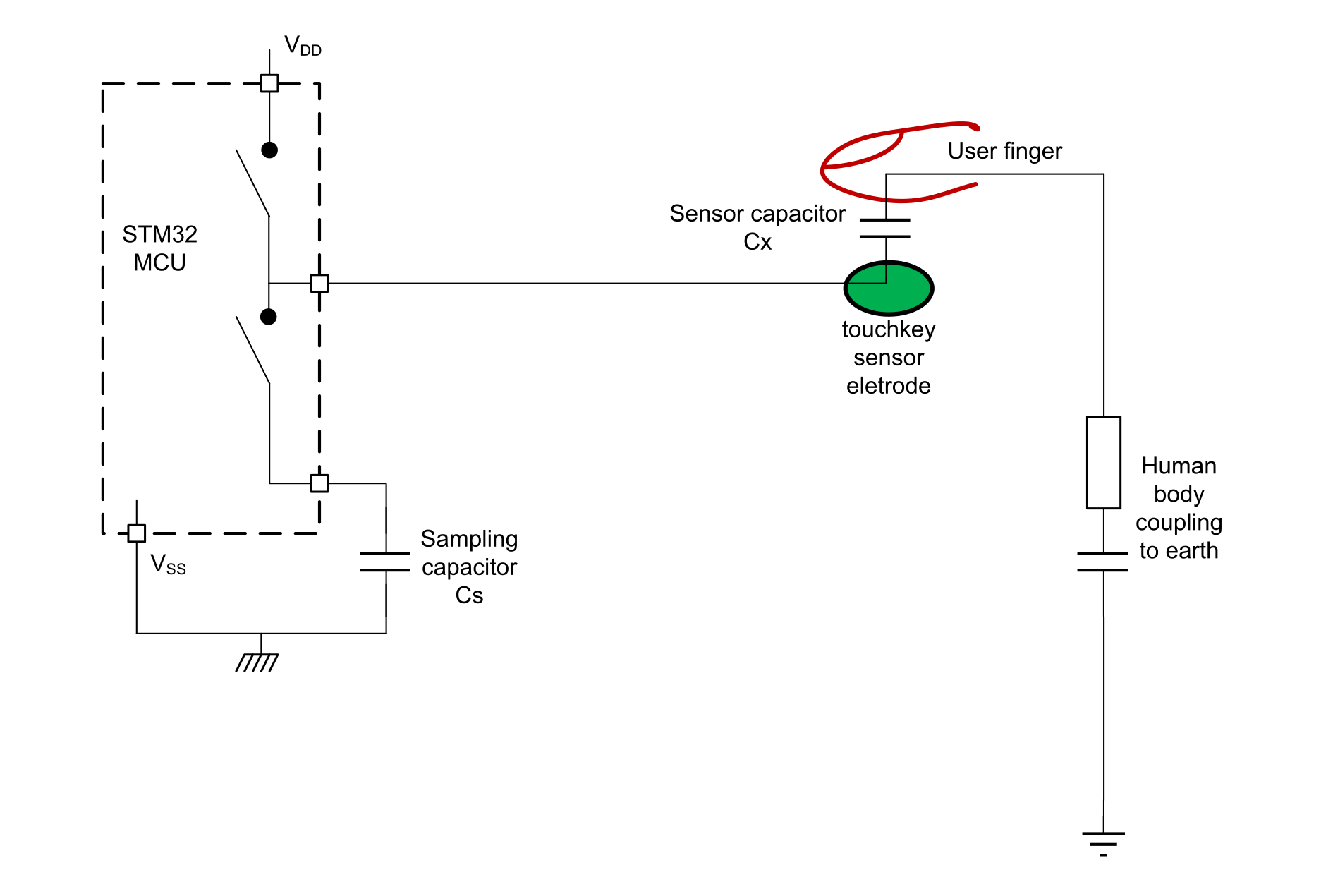
Table 2 Change transfer principle documentation gives a list of documents containing information about the change transfer principle.
| Id | Title | Chapters |
|---|---|---|
| AN4299 | Improve conducted noise robustness for touch sensing applications on MCUs | Surface charge transfer acquisition principle overview |
| AN4310 | Sampling capacitor selection guide for touch sensing applications on MCUs | Charge transfer acquisition principle overview |
| AN4312 | Design with surface sensors for touch sensing applications on MCUs | Capacitive sensing technology |
| AN4316 | Tuning a touch sensing application on MCUs | Charge transfer period tuning |
| OLT | STM32L4 online training | Touch sensing controller (TSC) |
Document reference
Figure 2 Main documentation tree shows the main documentation tree related to TSC and TSL.
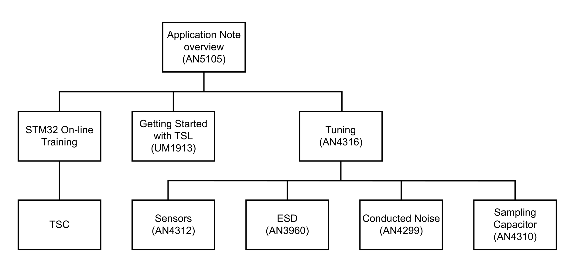
| Document name | Document title |
|---|---|
| UM1913 | Developing applications on STM32Cube with STMTouch touch sensing library |
| AN3960 | ESD considerations for touch sensing applications on MCUs |
| AN4299 | Improve conducted noise robustness for touch sensing applications on MCUs |
| AN4310 | Sampling capacitor selection guide for touch sensing applications on MCUs |
| AN4312 | Design with surface sensors for touch sensing applications on MCUs |
| AN4316 | Tuning a touch sensing application on MCUs |
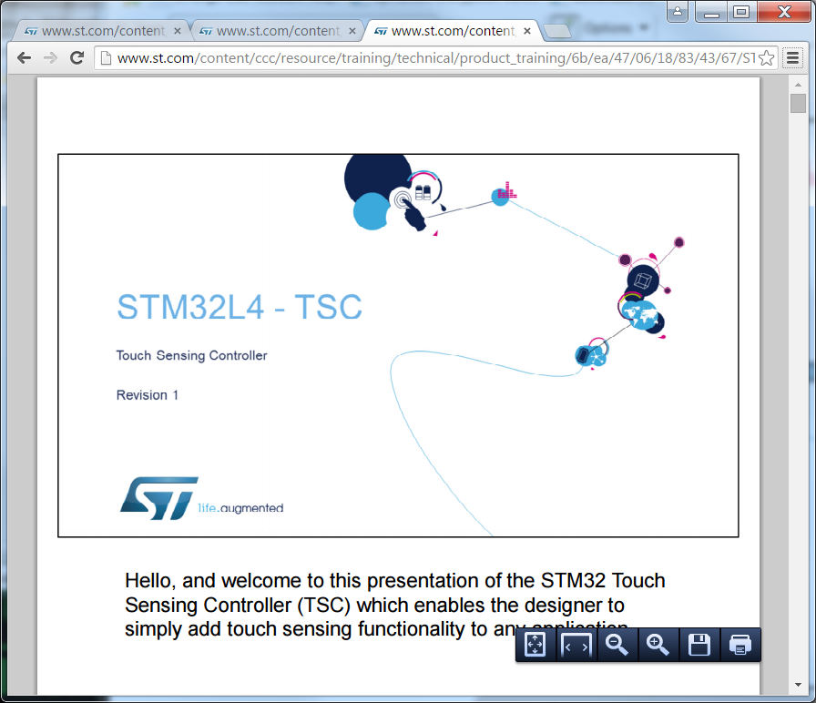
STM32L4 touch sensing controller online presentation
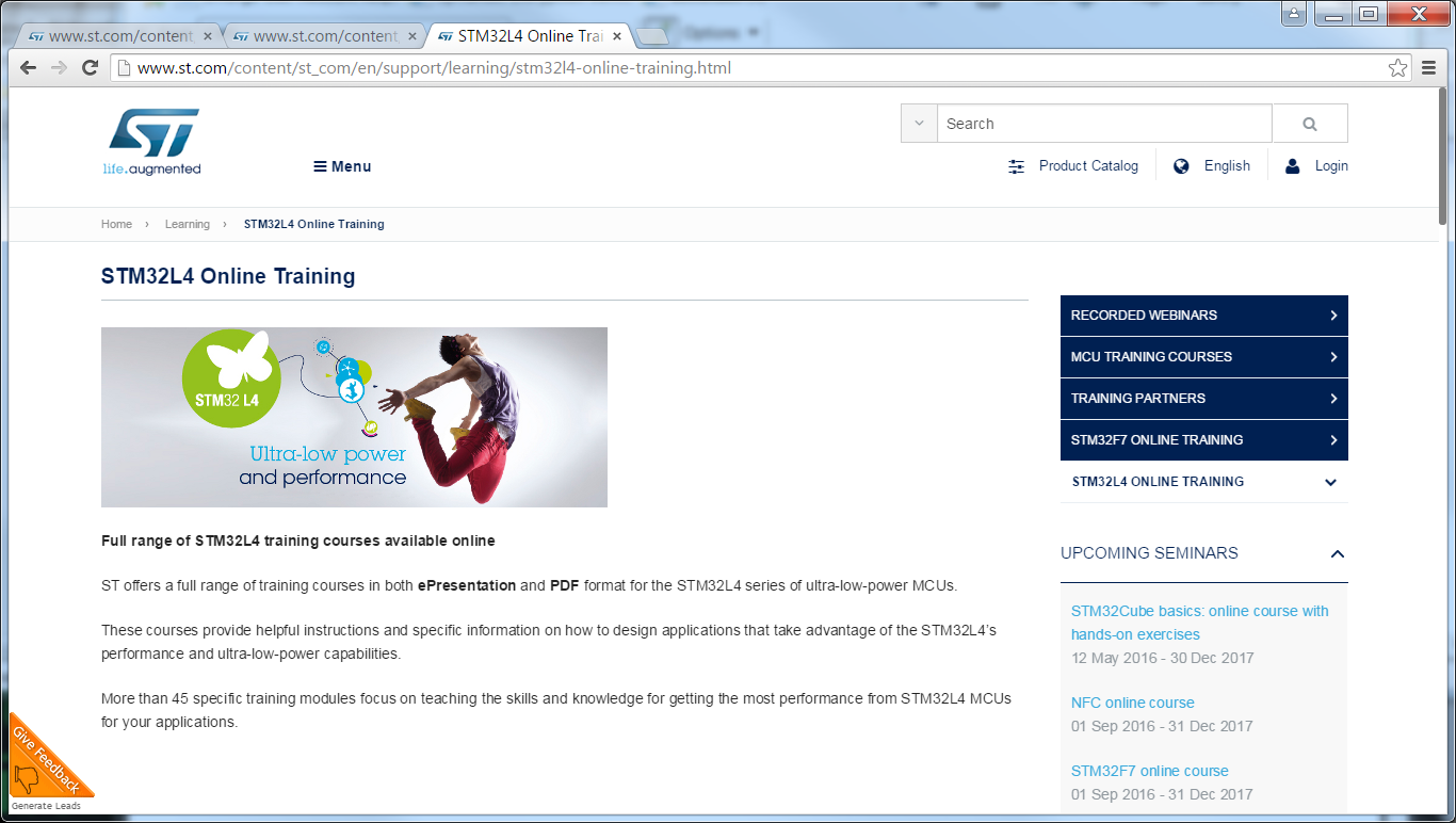
An online training is available from the STMicroelectronics website www.st.com.
Insert the "STM32L4 Online Training” string in the "Search" function and press enter.
To find it use the function "Search" and insert the strings “STM32L4 Online Training”. The figure below shows the online page available.
Main TSC characteristics
Description
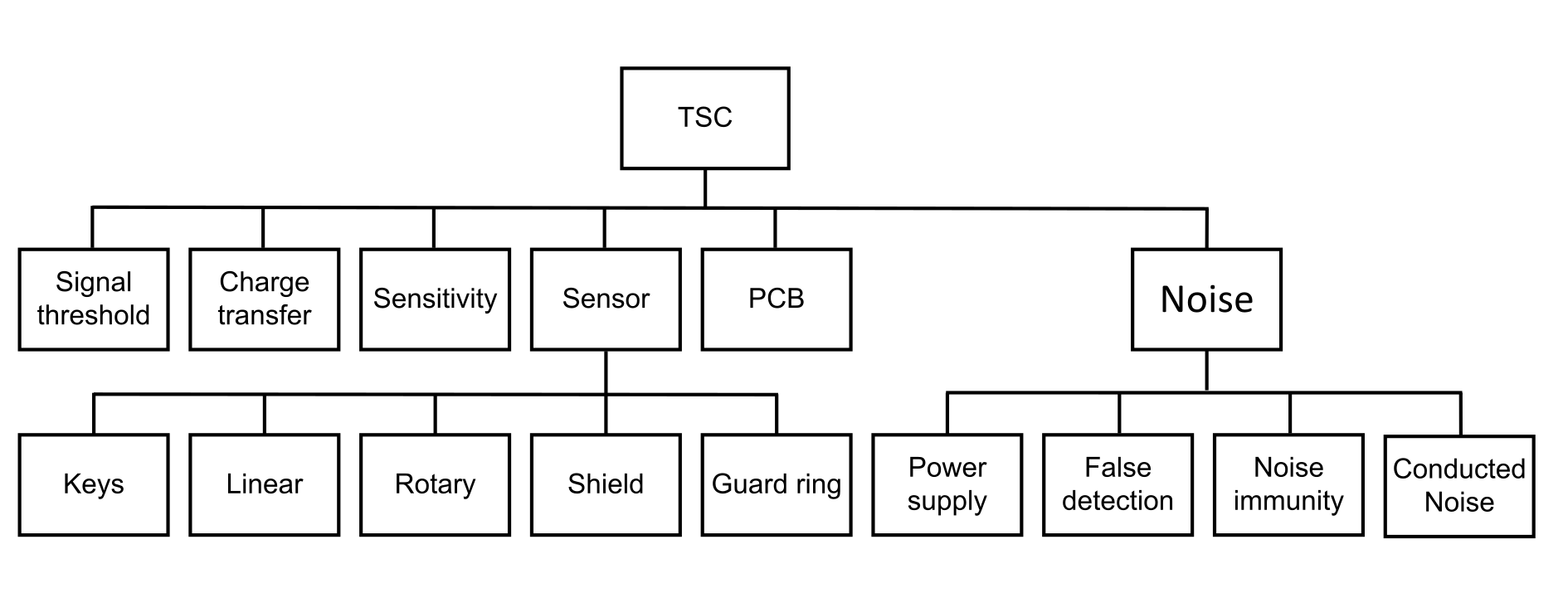
The following Figure 5 TSC characteristics shows all touch sensing controller (TSC) characteristics and their correlation.
The TSC main characteristics are described in the following pages.
Signal threshold
To tune the detection thresholds, it must determine the sensitivity of each touchkey. For each touchkey, can be used few parameters to adjust these signal thresholds.
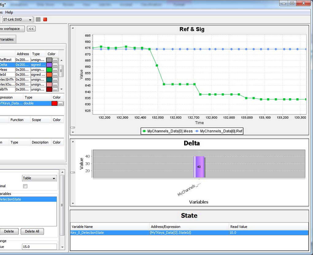
For debug purposes, it can get touchkey parameters using printf or the STMStudio tool:
  for (Index = 0;Index < NUMBER_OF_TOUCHKEYS;Index++)
  {
      printf("K%1d [%2d][%4d %3d %3d %4d] %d %d %d %d %d"
            ,Index
            ,MyTKeys[Index].p_Data->StateId
            ,MyTKeys[Index].p_ChD->Ref
            ,MyTKeys[Index].p_ChD->RefRest
            ,MyTKeys[Index].p_ChD->Delta
            ,MyTKeys[Index].p_ChD->Meas
            ,MyTKeys[Index].p_Param->ProxInTh
            ,MyTKeys[Index].p_Param->ProxOutTh
            ,MyTKeys[Index].p_Param->DetectInTh
            ,MyTKeys[Index].p_Param->DetectOutTh
            ,MyTKeys[Index].p_Param->CalibTh
            );
  }
Note:
ProxInTh and ProxOutTh are defined for the proximity detection feature only, when TSLPRM_USE_PROX = 1.
- On software side:
- Relevant information is available in tsl_conf.h and tscl_user.c files.
- Threshold (xx_TH) can be adjusted in tsl_conf_tsc.h file.
See below an example:
#define TSLPRM_TKEY_DETECT_IN_TH (64)
#define TSLPRM_TKEY_DETECT_OUT_TH (60)
#define TSLPRM_TKEY_CALIB_TH (56)
#define TSLPRM_LINROT_DETECT_IN_TH (50)
#define TSLPRM_LINROT_DETECT_OUT_TH (40)- The TSL api, tsl_user_SetThresholds, located in tsl_user.c allows the adjustment of each channel independently. See below an example:
void tsl_user_SetThresholds(void)
{
/* USER CODE BEGIN Tsl_user_SetThresholds */
  /* Example: Decrease the Detect thresholds for the TKEY 0*/
  MyTKeys_Param[0].DetectInTh -= 10;
  MyTKeys_Param[0].DetectOutTh -= 10;
 /* USER CODE END Tsl_user_SetThresholds */
  }
Table 4 Signal threshold use documentation gives a list of documents containing information about the signal threshold usage.
| Id | Title | Chapters |
|---|---|---|
| UM1913 | Developing applications on STM32Cube with STMTouch touch sensing library | Debug with STM Studio |
| AN4316 | Tuning a touch sensing application on MCUs |
Monitoring STMTouch driver variables using STM‑Studio Tuning the thresholds Touchkeys thresholds Linear and rotary touch sensors thresholds |