AN5105 · Application noteGetting started with touch sensing control on STM32 MCUs
Download .pdfOpen in the full document

Layout and PCB

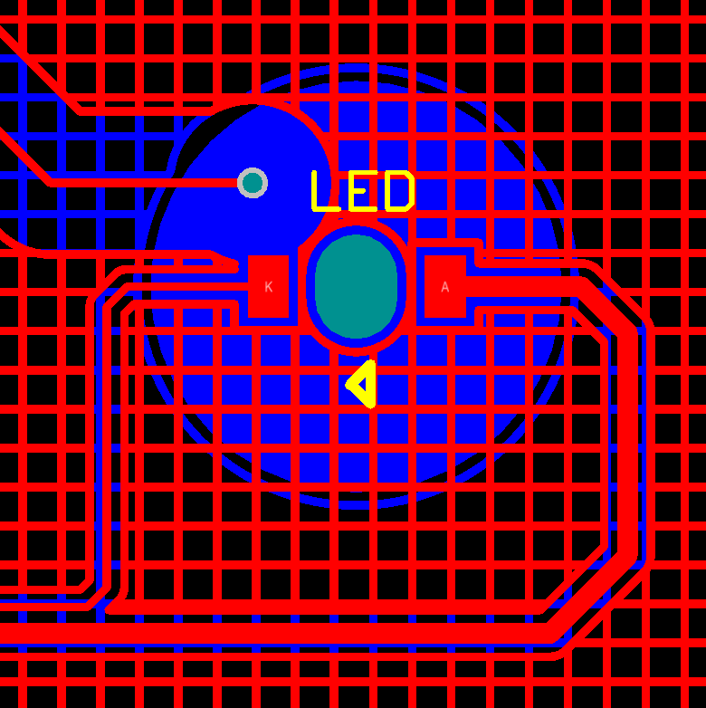
Led rules

Figure 12. Led layout example
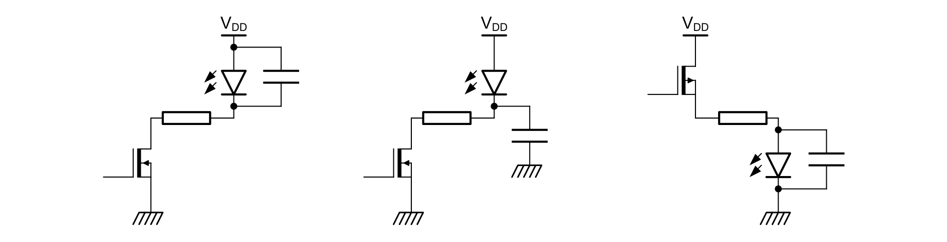
Figure 13. Example of cases requiring a LED bypass capacitor

Table 12 Led rules documentation gives a list of documents containing information about led rules.

Table 12. Led rules documentation
IdTitleChapters
AN4312Design with surface sensors for touch sensing applications on MCUs
  • LEDs and sensors
  • Placing of LEDs close to sensor

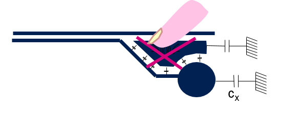
Electrode not located on PCB

It is possible but it is not recommended, because when the electrode it is not located on the PCB, the sensitivity decreases and additional extra parasitic capacitances are added.
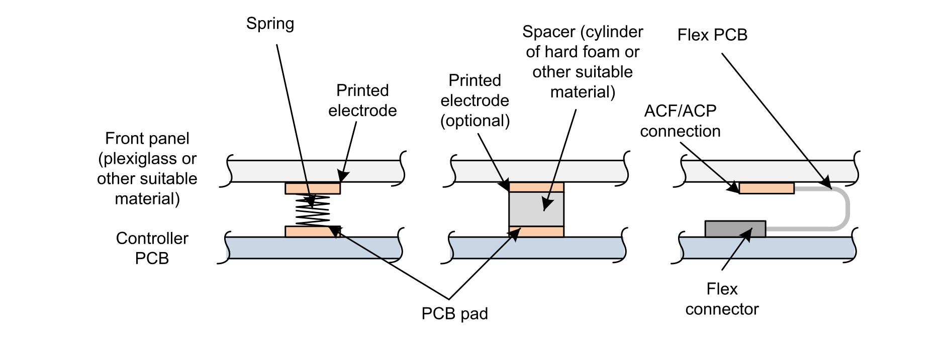
Figure 14. Electrode not located on PCB example

Table 13 Electrode documentation gives a list of documents containing information about the electrode.

Table 13. Electrode documentation
IdTitleChapters
AN4312Design with surface sensors for touch sensing applications on MCUsUsing electrodes separated from the PCB

Ground, shield and sensors

Table 14 Layout documentation gives a list of documents containing information about the layout.

Table 14. Layout documentation
IdTitleChapters
AN4312Design with surface sensors for touch sensing applications on MCUs
  • PCB and Layout
  • Ground considerations
  • Rotary and linear sensor recommendations

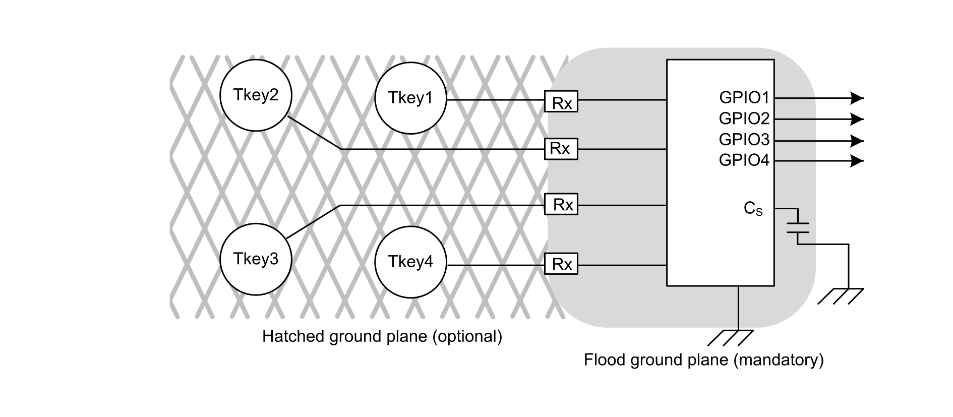
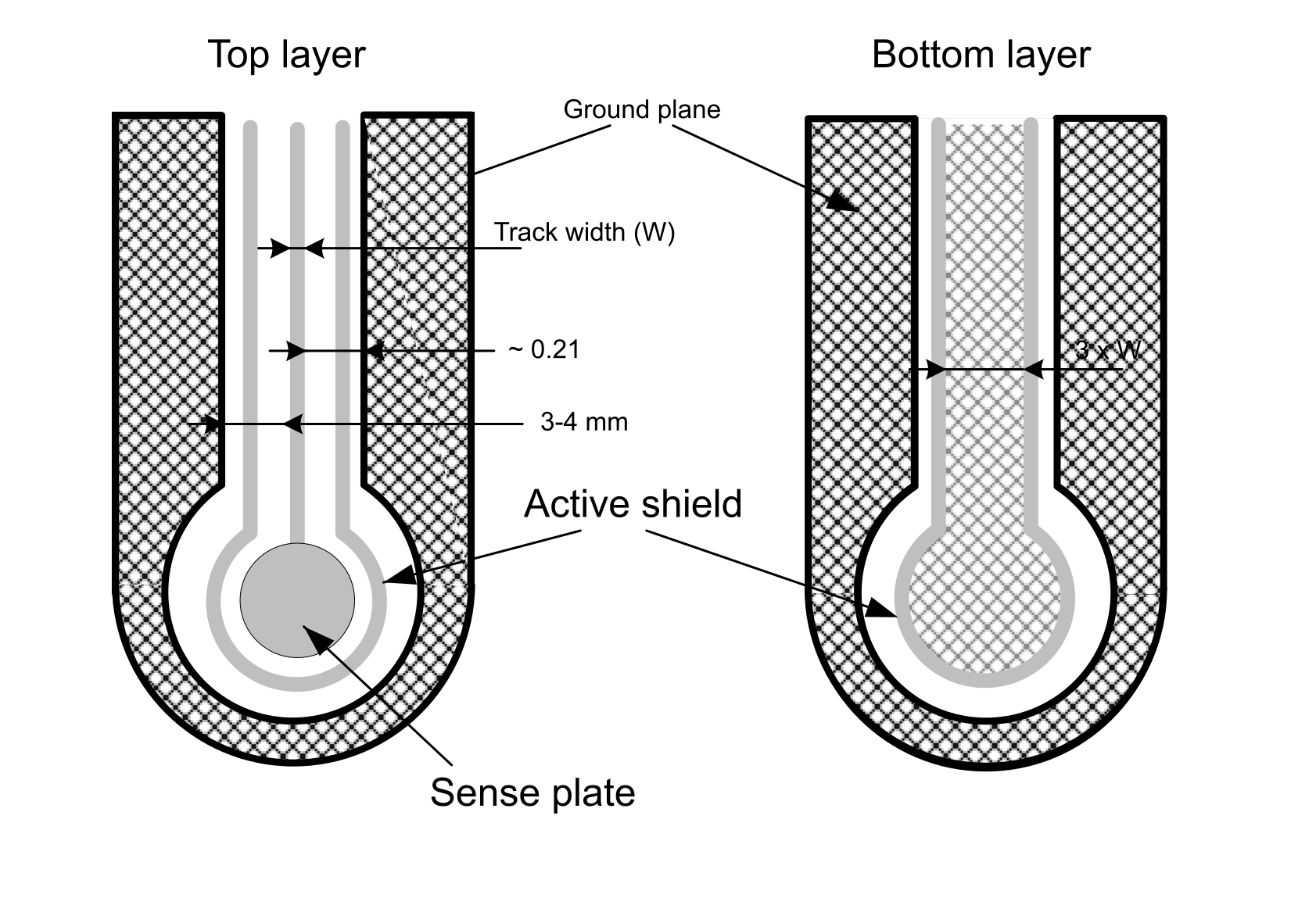
Figure 15 Hatched ground and signal tracks shows the ground plane and the signal tracks.
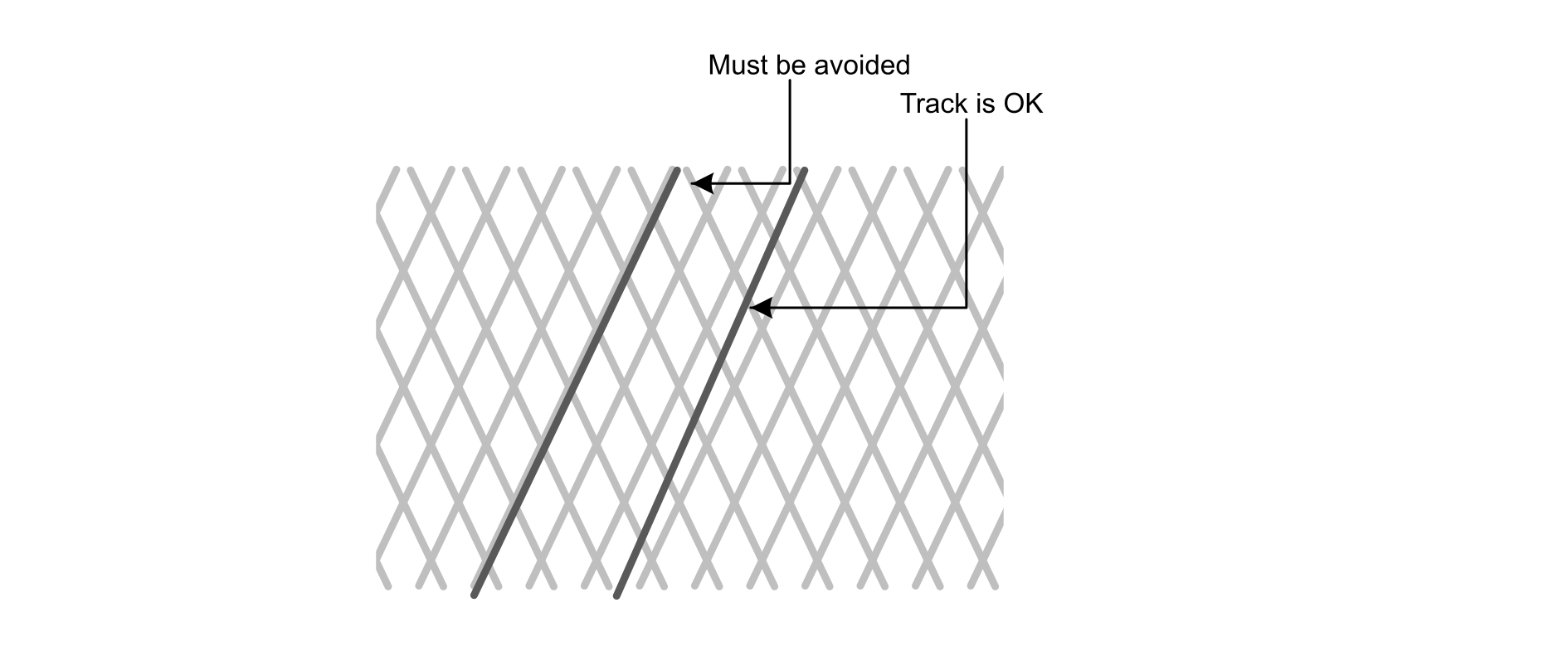
Figure 15. Hatched ground and signal tracks
Figure 16. Ground plane example
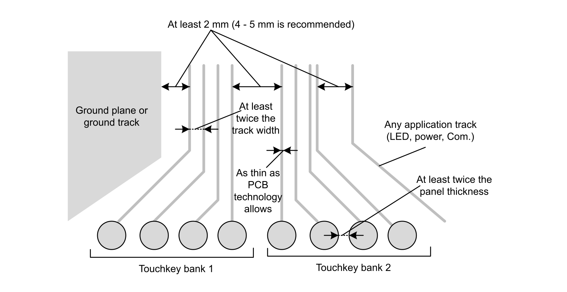
Figure 17. Track routing
Figure 18. Track routing recommendation
Figure 19. Shield

FAQ

System keys points:
  • Direct connection between earth and board ground is required to avoid conducted noise issues.
  • Conductive painting on the front panel must be avoided.
  • Robust mechanical assembly is required.

Layout keys points:

  • GND plane is mandatory under MCU, sampling capacitors and up to serial resistors
  • Hatched GND plane recommended for sensor traces from both sides of the PCB:
    • minimize parasitic capacitance
    • mesh plane possible with 25% to 40% copper
  • Route the sensors and ground on the same layer while the components and other tracks are routed on the other layers

Driven shield, or Active shield, is recommended.

  • If there are LEDs close to the sensors, to indicate a touch event, they must be bypassed by a capacitor whose typical value is 10 nF.
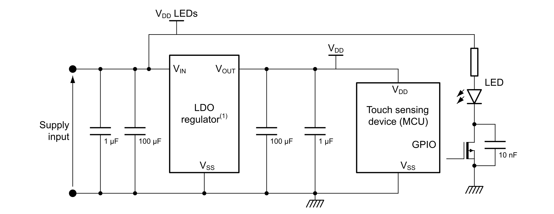
  • External LDO regulator should be used to power the MCU only to provide a stable power supply voltage without any ripple, especially all the switching components like transistors, LEDs, in the application must not be powered from the same voltage. This regulator should not be placed close to the sensors and their tracks, but close to the MCU.
  • It is strongly recommended to dedicate pins to be used as touch sensors and do not share them with other features

RS and CS keys points:

  • PPS or NPO sampling capacitors are recommended. Possible X5R or X7R.
  • Never use tantalium sampling capacitors.
  • Serial ESD 10 K (down to 1 K) resistors are recommended to be placed as close as possible to the MCU.
  • No track crossing or via between these resistors and the MCU.
  • The value of the sampling capacitor of the active shield should be different than the value of the sampling capacitors used for acquisition.
  • The capacitance of active shield is higher (larger area) than CX of a single touch sensing channel. In order to achieve the same waveform on active shield and active touch sensing channel, the ratios CS/CX of active shield and active touch sensing channel (touchkey). therefore, the CS of the active shield should also have higher value (k x CS of touch sensing channel).
Sensor key points:
  • Other traces must not cross the touch sensing traces or the whole touch sensing area
  • The touch sensing traces should be as thin as technology allows and as short as possible.
    • No longer than 10 cm
  • The space between traces and GND plane should be ideally 5 mm
  • TC pins are more robust against external interference than FT:
  • Consider modification of PCB layout to allow connection of external VDD clamping diode to touch sensing electrode traces.
    • Use low‐capacitance diode like BAR18, BAS70 with Cmax = 2 pF.
    • In case it is later needed, add pads and connection to the PCB without assembling components.
  • Floating panes must never be placed close to the sensors.

Power supply

Main rules to follow:

  • Place Buzzer and LED before LDO.
  • Place LDO close to MCU.
Figure 20. Typical power supply schematic

Table 15 Power supply documentation gives a list of documents containing information about the power supply.

Table 15. Power supply documentation
IdTitleChapters
AN4312Design with surface sensors for touch sensing applications on MCUsPower supply

False detection

To avoid false detection TSL embed ECS, DXS and DTO algorithms.

Table 16 False detection documentation gives a list of documents containing information about the false detection.

Table 16. False detection documentation
IdTitleChapters
UM1913Developing applications on STM32Cube with STMTouch touch sensing library
  • Environment change system (ECS)
    • Power supply voltage, temperature and air humidity
  • Detection exclusion system (DXS)
  • Detection time out (DTO)

Noise immunity

Noise filtering can be done on hardware and software (TSL) sides.

Table 17 Noise immunity documentation gives a list of documents containing information about the noise immunity.

Table 17. Noise immunity documentation
IdTitleChapters
UM1913Developing applications on STM32Cube with STMTouch touch sensing libraryNoise filters
AN4299Improve conducted noise robustness for touch sensing applications on MCUsHow to improve noise immunity
OLTSTM32L4 online trainingTouch sensing controller (TSC)

Conducted noise

  • Touch sensing systems require the conducted noise immunity.
  • A key point is the signal to noise ratio (SNR).
  • The test condition to be followed by the user is described in the standard IEC61000-4-6.

Table 18 Conducted noise documentation gives a list of documents containing information about the conducted noise.

Table 18. Conducted noise documentation
IdTitleChapters
AN4299Improve conducted noise robustness for touch sensing applications on MCUsAll chapters