AN5156 · Application noteIntroduction to security for STM32 MCUs
Download .pdfOpen in the full document

Life cycle management–product state

Life cycle management–product state

The addition of RDP 0.5 into the RDP mechanism used by the STM32 enabled the necessary isolation between secure and nonsecure development. However, the RDP does not allow going further in the user experience with the adoption of new development and OEM manufacturing models. The RDP has been replaced by the product state, a more refined life cycle management system, on the STM32H5 devices as a pilot project. The product state is also an answer to the needs of customers requesting a state that is effectively an RDP2 to the outside world and it allows them to perform a regression in the controlled environment. A similar provision was also added to the STM32U5 series, but the product state enabled finer control over delegating the debugging rights in TrustZone enabled products. It is sufficient for microcontrollers with no TrustZone isolation to use fewer states, for example, the STM32H7Rx/7Sx, which implement the product state this way.

The new life cycle management defines a set of permitted states, and the possible transition between them, just as in the case of the RDP, but there are more states defined for the following:
  • Provision with immutable root of trust code.
  • Clear separation of nonsecure and secure environment.
  • Use certificates for controlled regression.
  • Use certificates for temporary debug sessions.

For applications that do not need these new options, there are still product states corresponding to the original RDP values.

The main available product states are:
  • Open: roughly equivalent to RDP 0
  • Provisioning: marks an ongoing installation of iRoT
  • iRoT-provisioned: roughly comparable to RDP 0.5
  • TZ-closed: state in which debugging of nonsecure code is permitted
  • Closed: equivalent of RDP2, but the regression is possible (only with a valid authorization)
  • Locked: final state with no possibility of further transition (like RDP2)
Unique boot entry

If the secure boot firmware is located in the user flash, it is important to prevent the attacker from diverting the boot sequence from the intended progression. This is the goal of the unique boot entry or BOOT_LOCK.

The RDP2 on some products prevent booting from other memory. The BOOT_LOCK goes further by also working in RDP1 and working with the product state life-cycle management. In some devices the BOOT_LOCK allows the possibility to lock the boot to a specific address.

Even if RDP2 is set; the unique boot entry provides additional security assurance against glitch attacks.

A unique boot entry is available on STM32Ux, STM32Gx, STM32Hx, STM32Cx series, and in STM32WBA wireless devices. Implementation details are available in each device reference manual, on the sections about boot configuration and flash.

One-time programmable (OTP)

The OTP is a dedicated, isolated area in the flash memory, which can be only written on or locked out, preventing any modification. It is usually a smaller area compared to the size of the user flash memory.

This feature is very useful for lifecycle management, provisioning, personalization, or configuration. Once the OTP is written, there is no method of erasing data without physically damaging the device. No restriction is implicitly put on reading written data.

Note:

The OTP is available on most STM32 devices (refer to Overview for more details).

Boot and security control (BSEC)

On the STM32N6 series flashless microcontroller, the boot security and product state management are implemented using a large (12k) array of OTP fuses and data.

It is connected via core logic with debug interface, crypto, system bus, ST boot ROM, and clock control.

This system allows setting a 128-bit strong protection on debug access and product state including protection of the external program memory.

The OTP nature means increased security compared to regular flash memory, with acceptable drawback of limiting the re-usability of once provisioned device. OTP password were also used in product state protection on other popular devices.

Boot security is implemented so that the STM32N6 always boots in the ST boot ROM, which uses the OTP settings to execute the boot progression in configured manner.

TrustZone

This section describes the main features of the TrustZone® architecture. For further information, refer to the application note Arm® TrustZone® features on STM32L5 and STM32U5 series (AN5347), and to the device reference manual.

The Armv8-M TrustZone® architecture defines two domains at system level: secure and nonsecure. The full memory-map space is split into secure and nonsecure areas. This includes all memory types (flash memory, SRAM, and external memories), as well as all peripherals that can be shared (with specific context for each domain) or dedicated to one domain or the other.

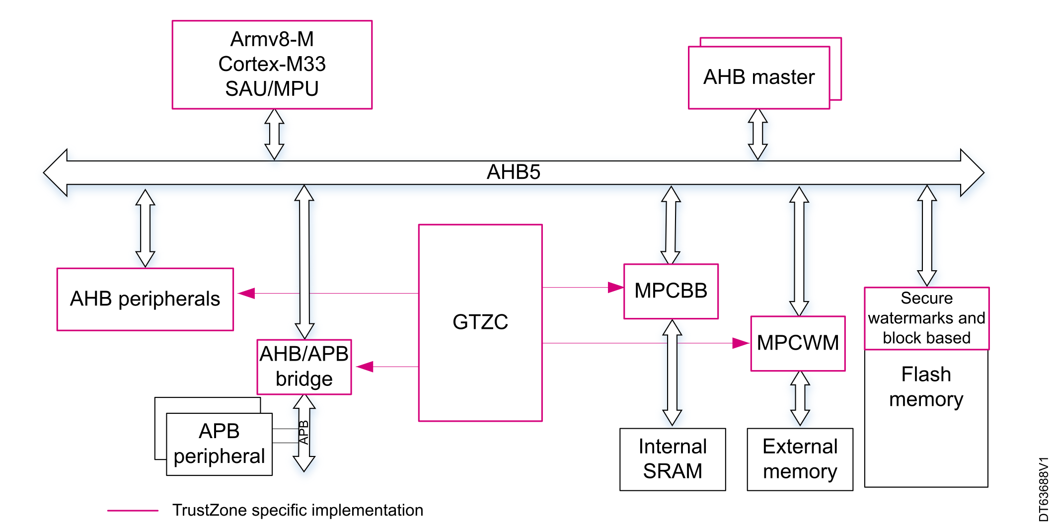
At system level, the isolation between secure and nonsecure domains relies on the following hardware mechanisms (see Figure 9 TrustZone® implementation at system level):
  • specific core architecture (Armv8-M Cortex-M33) with a dual execution domain for secure and nonsecure domains, and an implementation defined attribution unit (IDAU) to assert address range security status
  • secure attribution unit (SAU) is used to refine settings of the IDAU
  • bus infrastructure that propagates the secure and privilege attributes of any transaction (AHB5)
  • dedicated hardware blocks managing the split between the two domains (GTZC to define security attribute for internal SRAMs and external FSMC/OCTOSPI memories, and peripherals)
Figure 9. TrustZone® implementation at system level

Core state

The core state depends on the region of the current running code. When the code runs from a secure region, the core is in secure state. Otherwise, the core is in nonsecure state.

Secure attribution unit (SAU)

The SAU is a hardware unit coupled to the core (as the MPU). The SAU is responsible for setting the security attribute of the AHB/AXI transaction. The security attribute of a transaction is fixed by the targeted address of a memory-mapped resource (memory areas or peripherals). Depending on the SAU configuration, an address is tagged as secure, nonsecure callable (NSC), or nonsecure. The NSC is a subdomain of the secure domain that allows a gateway to be defined for nonsecure code to access the secure domain at a specific entry point.

The SAU is configurable by secure firmware. It can be configured at boot for a fixed configuration, or can be dynamically modified by a secure firmware.

Note:

A security attribute cannot be modified to be less secure (by security order: secure > NSC > nonsecure) than a default attribute set by hardware through an IDAU (implementation defined secure attribute). Refer to implementation details of each device in the reference manual.

Address aliasing

The security attribute is set depending on the fixed resource address. However, a memory‑mapped resource can be set either as secure or nonsecure, depending on the application. To overcome this apparent contradiction, two addresses are assigned to each memory-mapped resource: one used when the resource must be accessed in secure mode, one used in nonsecure mode. This mechanism is called address aliasing.

The address aliasing also allows all peripheral accesses to be grouped in only two regions instead of multiple scattered regions. Finally, the IDAU splits the memory-mapped resources in the following regions:
  • Peripherals secure/nonsecure regions
  • Flash memory secure/nonsecure regions
  • SRAM secure/nonsecure regions

Refer to device reference manual for the detailed configuration.

Memory and peripheral protections

The SAU defines the transaction security attribute, and the bus infrastructure propagates this attribute towards the targets. The targets (memories and peripherals) are protected by hardware mechanisms that filter the access depending on the secure and privileged attributes.

There are two types of peripherals in the TrustZone® system architecture:
  • TrustZone®-aware peripherals: connected directly to the AHB or APB bus, with a specific TrustZone® behavior such as a subset of secure registers. The access filtering control is included in these peripherals
  • Securable peripherals: protected by an AHB/APB firewall gate controlled by the GTZC to define security properties

TrustZone®-aware peripherals are the ones with a bus master role (DMAs), the GTZC, the flash memory controller, and others peripherals with a fundamental role within the system (PWR, RTC, system configuration). The remaining system peripherals are securable.

The GTZC defines the access state of securable peripherals, embedded SRAM, and external memories:
  • Peripherals can be set as secure or nonsecure (exclusively), privileged or unprivileged using TZSC.
  • Embedded SRAM is protected by blocks of 256 bytes through the MPCBB.
  • External memories are protected by regions (watermark: start and length). The number of protected regions depends on the memory types (NAND, NOR, or OCTOSPI).
  • Illegal access events lead to secure interrupts generated by TZIC.
Note:

The flash memory security attribute is defined through secure watermark option bytes, and/or flash memory interface block-based registers.

Flash memory write protection (WRP)

The write protection feature is used to protect the content of the specified memory area against erase or update.

For flash memory technology, an update must be considered as filling with zeros.

For instance, the write protection can be set on a page or a sector of a flash memory to prevent its alteration during a firmware or data update. It can also be set by default on the unused memory area to prevent any malware injection. Its granularity is linked to the page or sector size.

When to use the WRP

This protection must be used, in particular when write operations are foreseen within the application. This is the case if data storage or code update operations are expected. The WRP prevents wrong accesses due to unsafe functions causing unexpected overflows.
Note:

The WRP is available on all STM32 devices with internal flash memory.

Execute-only firmware (PCROP)

Part of the STM32 flash memory can be configured with an 'execute-only' attribute. The firmware stored in such configured area can only be fetched by the CPU instruction bus. Any attempt to read or write this area is forbidden. The protection applies against both internal (firmware) accesses as well as external (debug port) accesses. In an STM32 device, this feature is named proprietary code readout protection (PCROP).

The PCROP is a static protection set by option bytes. The number of protected areas and their granularity depends on the STM32 device (see Security features by STM32 devices). When the PCROP is in use, care must be taken to compile the firmware with the execute-only attribute (refer to user compiler options). Refer to the document AN5156_General-Info.html#concept_vts_yqx_fcb__entry_jh2_brz_qvb for more details.

In particular, the ARMv6-M instruction set has difficulty working with this constraint. The compiler must be set not to place constants and literal pools within the program, otherwise even the code execution can eventually trigger the protection.

When to use the PCROP

The PCROP is used to protect third-party firmware (intellectual property), as well as the most sensitive parts of the user firmware.
Note:

The PCROP is available on all STM32 devices listed in Table 1, except on TrustZone-enabled devices, where it is superseded by another protection mechanism.

Secure hide protection (HDP)

Some STM32 devices support the HDP memory concept. The HDP, named secure hide protection first on STM32L5 devices, is also known as secure user memory on STM32H7 devices, or securable memory on STM32G0 devices.

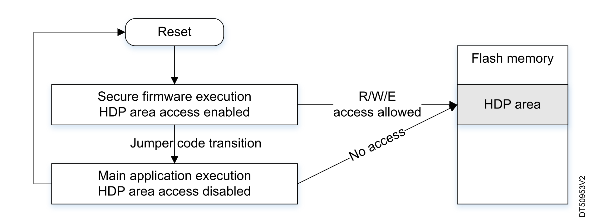
An HDP area is a part of the user flash memory that can be accessed only once, just after a device reset. The HDP targets sensitive applications that embed or manipulate confidential data, and that must be securely executed at boot. Once the transition is executed, the HDP area is closed, and cannot be accessed anymore by any means (see the figure below).

The code that facilitates the HDP transition is usually a STMicroelectronics code located in the RSS. Code in SRAM is an alternative.
Figure 10. HDP protected firmware access

The HDP is a static protection configured by option bytes. Once set, the CPU boots on the firmware embedded in this area, independent of the boot configuration set by boot pin or boot address. HDP can be single stage or use a monotonic counter to gradually cover more memory as the secure boot progresses (STM32H5). Some devices implement a dynamic HDP expansion. This means that the HDP can be extended by the number of sectors using the register value, without programming the OB (STM32H5, STM32U0).

When to use the HDP

The HDP is suited for a code that must only be executed after reset, like secure boot for root of trust. It should be used in synergy with the boot lock feature.
Note:

The HDP is available in STM32H7, STM32G0, STM32G4, STM32L5, STM32N6, STM32U0, STM32U3, STM32U5, and STM32H5 devices, with slight differences in its implementation and name (refer to the reference manuals for details).