AN5156 · Application noteIntroduction to security for STM32 MCUs
Download .pdfOpen in the full document

Software isolation

Software isolation

The software isolation refers to a runtime mechanism protecting different processes from each other (interprocess protection). These processes can be executed sequentially or concurrently (for example tasks of operating system). The software isolation in the SRAM ensures that respective stack and working data of each process cannot be accessed by the other processes. This interprocess protection can be extended to the code in the flash memory and nonvolatile data as well.

Goals of the software isolation:

  • Prevent a process to spy the execution of another sensitive process.
  • Protect a process execution against a stack corruption due to memory leaks or overflow (incorrect memory management implementation).
This memory protection can be achieved through different mechanisms listed in the table below, and detailed in STM32 security features.
Table 7. Software isolation mechanism
ProtectionTypeIsolation
MPUDynamicBy privilege attribute 1
FirewallStaticBy bus address hardware control
Secure hide protection (HDP)StaticProcess preemption at reset
Dual coreStaticBy core ID2
TrustZone®/Security attributeStatic and dynamicBy secure attribute propagated from the core to all resources
1 The attribute protection is only for CPU access and is not taken into account for other bus master (such as DMA).
2 Reading the CPUID indicates which CPU is currently executing code. An example can be found in the HAL_GetCurrentCPUID function.
Debug port and other interface protection

The debug ports provide access to the internal resources (core, memories, and registers) and must be disabled in the final device. It is the most basic external attack that is easily avoided by deactivating JTAG (or SWD) ports by a secure and immutable firmware (refer to Secure boot (SB)), or preferably by permanently disabling the functionality (JTAG fuse in RDP2, life cycle protection).

Other serial interfaces can also be used. If the bootloader is available, the device content can be accessed through I2C, SPI, USART, or USB‑DFU. If the interface is open during the runtime, the application transfer protocol must limit its access capabilities (such as operation mode or address access range).

Associated STM32 features:

Boot protection

The boot protection secures the very first software instructions in a system. If an attacker succeeds in modifying the device boot address, he/she can execute his/her own code, to bypass initial dynamic protections configuration or to access unsecured bootloader applications that give access to the device memory.

A microcontroller usually allows the boot configuration in order to choose between starting at user application, at bootloader application, or at the SRAM located firmware. The boot protection relies on a single entry point to a trusted code that can be the user application, or a secure service area if available (RSS).

Associated STM32 features:

System monitoring

The monitoring of the device power supply and environment can be set to avoid malfunction and to take corresponding countermeasures. Some mechanisms, like tamper detection, are dedicated to security. Other mechanisms are primarily used for safety reason but can serve security as well. For example, the detection of a power down or external clock disconnection can be unintentional (safety) but can also reveal an attack (security).

Tamper detection is used to detect system/board level intrusions. The opening of a consumer product enclosure can be detected on an MCU pin and trigger appropriate actions. Internal tamper sensors can detect irregular voltage, temperature, or other parameters.

Clock security system is used to protect against external oscillator failures. If a failure is detected on the external clock, the microcontroller switches to the internal clock to safely execute. The interrupt signal allows the firmware to react to the clock failure event.

Power supply and voltage level can be monitored to detect an abnormally low voltage level. Below a certain voltage value, the normal behavior cannot be ensured and it may be the sign of a fault injection attack.

Device temperature can be measured with an internal sensor. The information is fed back to the device through an internal ADC channel. A monitoring application can take appropriate actions according to the temperature range. Increased temperature may be part of a fault injection attack scheme.

Associated STM32 features:
  • Tamper protection (with RTC component)
  • Clock security system
  • Power supply supervision
  • Temperature sensor

Secure applications

To create a secure system, the hardware features must be used in a secure firmware architecture implementation. An industry-standard solution is the PSA, proposed by Arm for the IoT ecosystem. The STMicroelectronics proprietary solution is secure boot (SB) and secure firmware update (SFU). It is possible to use secure firmware installation (SFI) to securely provision blank devices in manufacturing.

This section defines the root and chain of trust concept before presenting the following typical secure applications implementing the features listed below:
  • Secure boot
  • Secure firmware update
  • Secure storage
  • Cryptographic services

These applications have a close link with cryptography. All cryptographic schemes are based on the three concepts of secret key, public key, and hashing. The basics of cryptography are explained in Cryptography–Main concepts. Cryptography–Main concepts.

Note:

Secure firmware install (SFI)

In a mass production scenario, there may be concerns to get secure binaries to the parts without exposing them to an untrusted environment.

In the SFI scenario, the binaries are encrypted using STM32 Trusted Package Creator software tool and sent to HSM within the production facility, to install the code in the microcontrollers.

Note:

See AN5391 AN5156_General-Info.html#concept_vts_yqx_fcb__ph_15, AN5054 AN5156_General-Info.html#concept_vts_yqx_fcb__ph_16, and AN4992 AN5156_General-Info.html#concept_vts_yqx_fcb__ph_17 for more information.

SFI is supported on STM32L4, STM32L5, STM32U3, STM32U5, STM32H5, STM32N6, STM32WBA, STM32WL, and STM32H7 series.

Root and chain of trust

The principle of root and chain of trust is common to many secure systems. It is obviously scalable ad libitum, inherently efficient and also flexible.

A chain of trust is built as a set of applicative components in which the security of each component is guaranteed by another component. The root of trust is the anchor at the beginning of the chain on which the overall security depends.

The secure boot implementation must be the single entry point to the device, start after reset with immutable code in secure mode. It then authenticates a subsequent functionality and executes the next part of the firmware that enables the additional functionality required to securely attest the following chain link. For example, it configures volatile memory protection, so that a secure storage service can use it.

For more details about STiRoT immutable Root of Trust, see AN6007 AN5156_General-Info.html#concept_vts_yqx_fcb__ph_14.

Secure boot (SB)

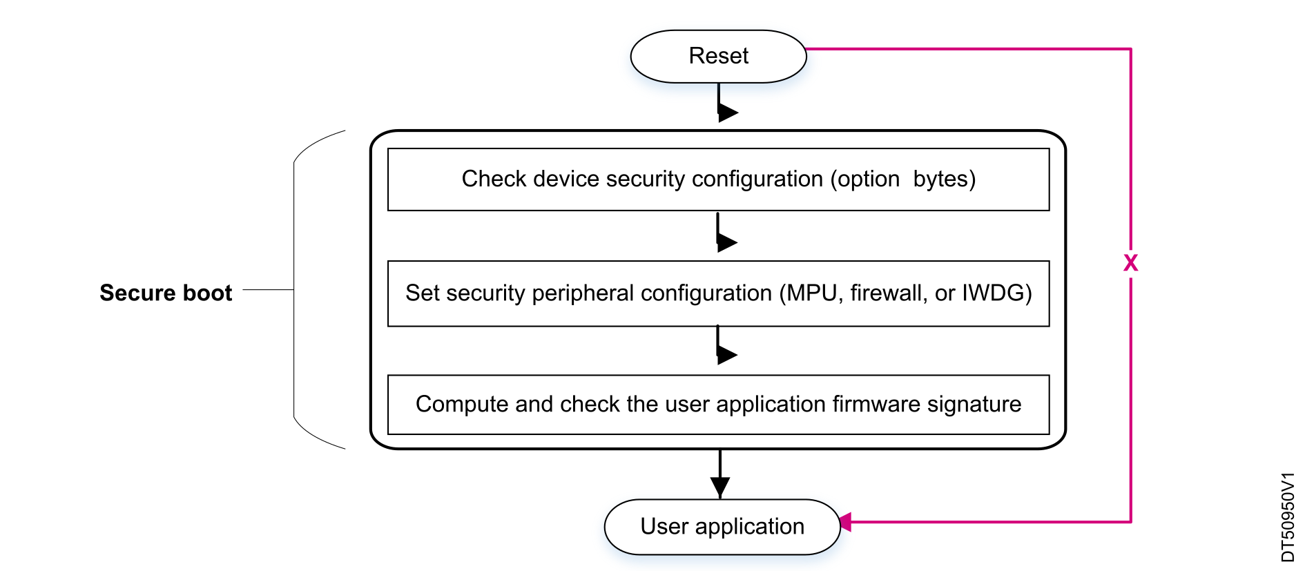
The SB application is executed at reset before the user application. It provides first stages of security, and is then responsible for ensuring the global chain of trust of the system.

SB main functionalities:
  • Check the STM32 security configuration and set up runtime protections.
  • Assert the integrity and authenticity of the user application images that are executed (see the figure below).
Figure 6. Secure boot FSM

Device security check

This part of the SB application checks if static configurations are correct, and sets the dynamic ones. Static secure configurations are defined by option bytes (RDP, PCROP, WRP, and HDP). Dynamic protections must be programmed (firewall, MPU, tamper detection, and IWDG).

Integrity and authenticity check

The firmware integrity is performed by hashing the application image (with MD5, SHA1, or SHA256 hash algorithms), and comparing the digest with the expected one. This way, the application firmware is considered error-free.

An authenticity check is added if the expected tag is encrypted with a key shared between the firmware owner and the device. This key is stored in a protected area of the device.

Protection attributes

The SB firmware must have the following attributes to fulfill its role:
  • It must be the device-unique entry point (no bypass).
  • Its code must be immutable.
  • It must have access to sensitive data (such as certificates or application signatures).

The most sensitive SB part takes benefit from process and data isolation features, like firewall, MPU, or secure hide protection. The implementation depends on the STM32 available features.

Secure firmware update (SFU)

The SFU provides a secure implementation of in-field firmware updates, enabling the download of new firmware images to a device.

The firmware update is a sensitive operation that must protect two parties:
  • the device owner: the goal is to avoid loading a corrupted firmware (intentionally or not) that can damage the device.
  • the application owner (OEM): needs to protect his firmware from being cloned or loaded into an unauthorized device.

Architecture

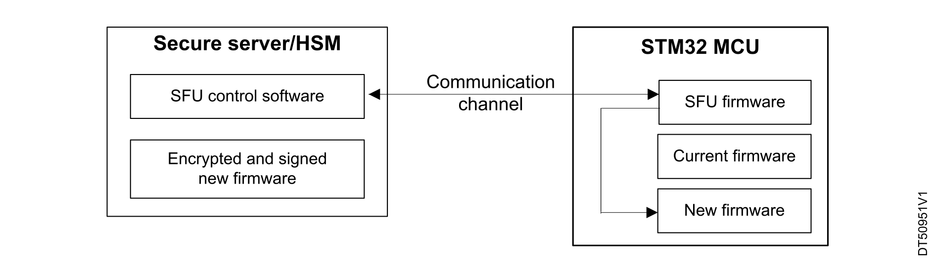
An SFU transfer involves two entities: the firmware owner (OEM) and the device to be updated (see the figure below). As the communication channel is generally considered as nonsecure since it is subject to eavesdropping, the overall security responsibility is shared between the sender (firmware owner server) and the receiver (the device).
Figure 7. Secure server/device SFU architecture

Application

From OEM side, a secure server is maintained that is responsible for sending the encrypted (if confidentiality is required) and signed firmware to an authenticated device.

The SFU application running on device is in charge of the following:
  • authentication and integrity checking of the loaded image before installing it
  • decrypting the new firmware if confidentiality is required
  • checking the new firmware version (anti-rollback mechanism)

Configurations

The ST proprietary SBSFU is very configurable. The most important configuration option is the choice to use a single or dual image handling of application code. Each has a separate example. Single image leaves more space for application code. Two or more images add some advanced features to the image handling.

The second most important option is the cryptographic scheme selection. There are usually the following choices:
  • ECDSA asymmetric cryptography for firmware verification with AES-CBC or AES-CTR symmetric cryptography for firmware encryption
  • ECDSA asymmetric cryptography for firmware verification without firmware encryption
  • X509 certificate-based ECDSA asymmetric cryptography for firmware verification without firmware encryption
  • AES-GCM symmetric cryptography for both firmware verification and encryption

For more details, see the document AN5156_General-Info.html#concept_vts_yqx_fcb__entry_nsy_brz_qvb or the document Integration guide for the X‑CUBE‑SBSFU STM32Cube Expansion Package (AN5056).