AN5156 · Application noteIntroduction to security for STM32 MCUs
Download .pdfOpen in the full document

Device protections

Device protections

Security protections described in this section are controlled by hardware mechanisms. They are set either by configuring the device through option bytes, or dynamically by hardware component settings:
  • Memory protection: main security feature, used to protect code and data from internal (software) and external attacks
  • Software isolation: inter-processes protection to avoid internal attacks
  • Interface protection: used to protect device entry points like serial or debug ports
  • System monitoring: detects device external tampering attempts or abnormal behaviors
Configuration protection

Any persistent security configuration is stored in a dedicated area of the non-volatile memory, called option bytes (OB). The option bytes are protected with redundancy, and, in case of perceived vulnerability, they are stored as a “magic value”. Besides rules imposed by security logic (OB can only be changed under specific conditions), there are rules to determine the default value in case of OB corruption.
Note:

Magic value is a pattern of usually 8 bits that must be exactly matched for the value to be recognized as valid, common examples are 0xB4 or 0xC3 for TRUE or FALSE.

Details about rules to modify the option bytes are detailed in each reference manual. The configuration is generally frozen by raising the RDP level. Additional rules apply case-by-case.

Each OB value is preconfigured to a reset value in production. This value is usually the least secure, open option. In case of an error detected in OB loading (OBL, happens on every POR or request), the configuration is set to a default value. This default value usually sets the highest possible security level to prevent leaking information from damaged microcontroller.

It is useful to analyze the impact of a configuration error on an application, and to plan for potential recovery. Highest number of corrupted option bytes however result of errors in programming. If the OB are modified in controlled environment, the threat of unintentional device locked-up is very low.

TrustZone® for Armv8-M architecture

Microcontrollers based on Armv6 or Armv7 architecture (Cortex-M0, M3, M4, and M7) rely mostly on software implementations for firmware and resource isolation. These mechanisms, described later in the document, are robust but not capable of isolation of secure firmware like operating system from installed applications with nonsecure firmware.

The Armv8-M architecture brings a new security paradigm in Arm microcontrollers. It implements the TrustZone® technology at microcontroller system level, allowing the development of trusted firmware through a robust isolation at runtime.

The TrustZone® technology relies on a processor (Cortex-M23, Cortex-M55 or Cortex-M33) separation for secure and nonsecure domains and on a bus infrastructure (AMBA®) propagating secure attribute throughout the whole system (peripherals and memories).

The TrustZone® is made for robust and flexible security control at runtime. Switching from secure to nonsecure domain and vice versa is straightforward with few cycle penalties. There is no need for a Secure monitor as in TrustZone® for application processors Cortex‑A.

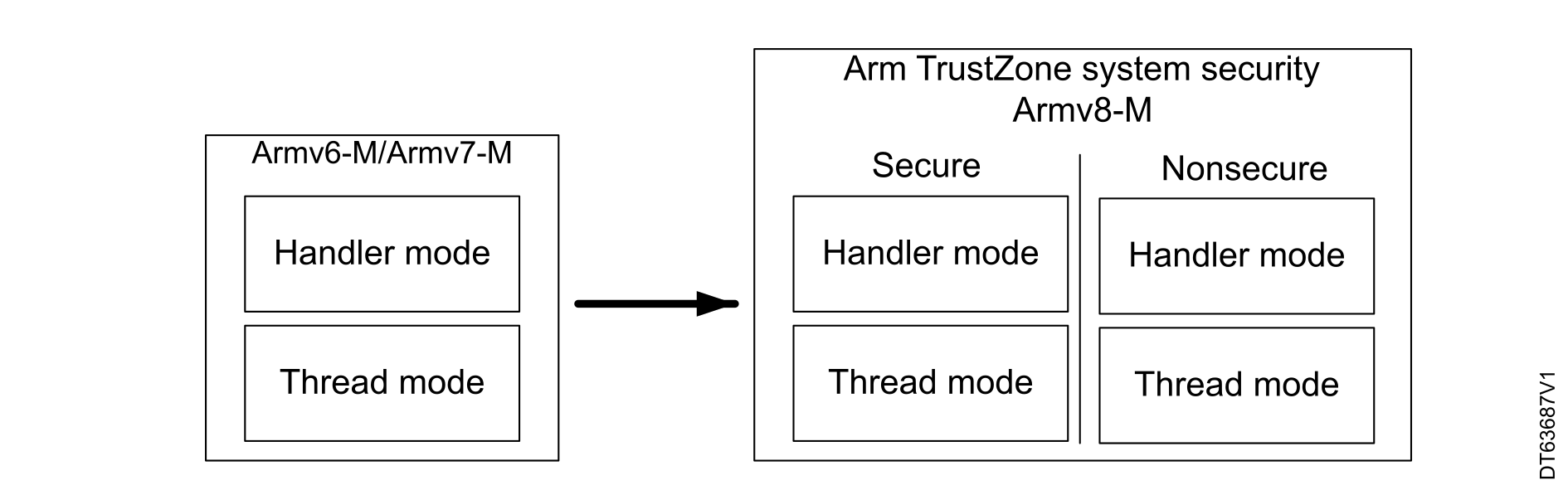
Secure modes are orthogonal to the existing modes, Thread and Handler. Thus, there can be a Thread or Handler mode in each secure mode (see the figure below).
Figure 3. Armv8-M TrustZone® execution modes

On typical firmware architecture running on Armv8 TrustZone®, the nonsecure domain executes the application and the OS tasks, while the secure domain executes the secure application and the system root-of-trust mechanisms.

Dual-core architecture

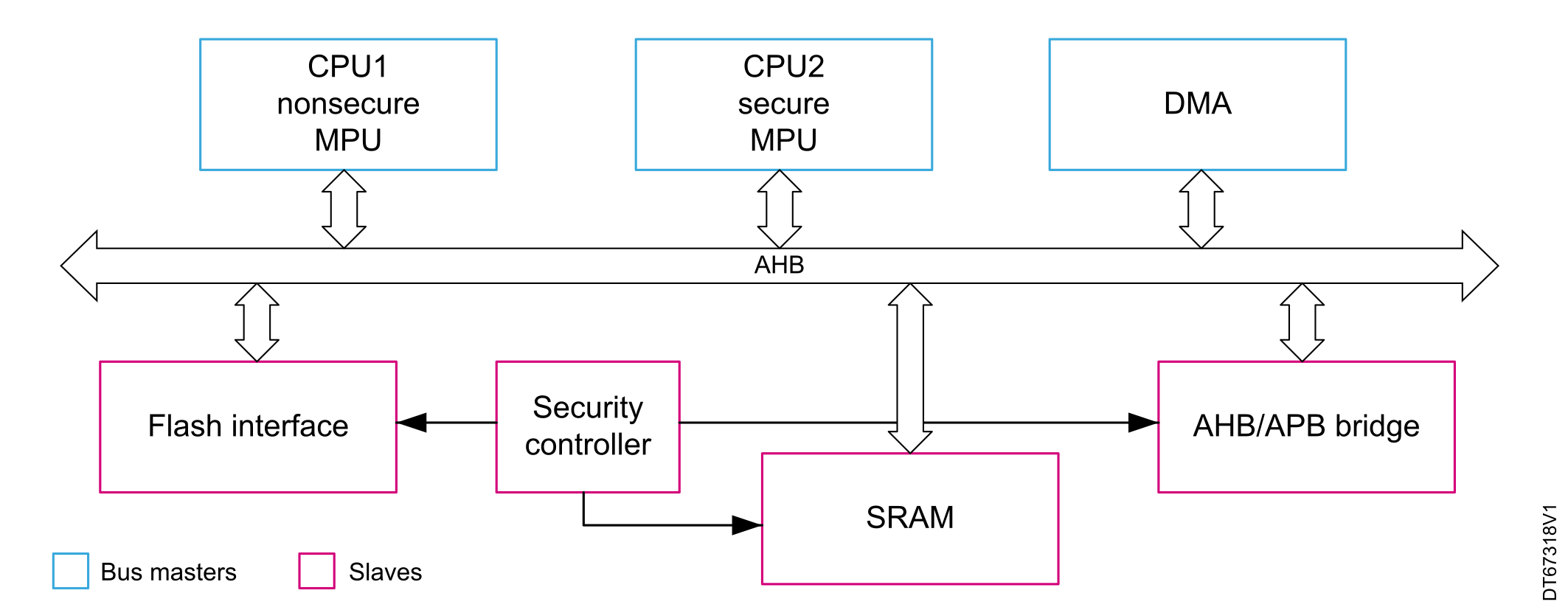
In dual-core products, one core can act as secure while the other is nonsecure. Some products, such as dual‑core STM32WL devices in particular, feature a hardware support to propagate the secure attribute to memory and peripherals, ensuring that robust runtime isolation implementation is possible.

A dedicated security controller is added to the dual-core STM32WL devices to facilitate the isolation.

Instead of using attribution units, the secure NV memory dedicated to securable CPU2 is defined in the flash memory interface configuration. Key peripherals such as the DMA must convey the secure context (refer to the user manual Getting started with STM32CubeWL for STM32WL series (UM2643) for details about this hybrid architecture).

Figure 4. Simplified diagram of dual-core system architecture

Memory protections

Storage containing sensitive code and data must not be accessible from any unexpected interface (debugging port) or an unauthorized process (internal threat).

Depending on the asset to be protected (code or data), various mechanisms can be set to establish protections at the source of the unauthorized access (external port, internal process) or on the memory type to be protected (flash, SRAM, or external memory).

Part of the access filtering can be performed by the memory interfaces (like flash controller), the bus controller peripheral (firewall, RIF, and more), or through the core MPU if it is available. Where applicable, Armv8 security isolation features are used. Details on proprietary protections (secure hide protection, PCROP, WRP, RDP) can be found in STM32 security features.

Embedded flash memory, embedded SRAM, and external memories are designed for different purposes. Their respective protections mechanisms reflect these differences.

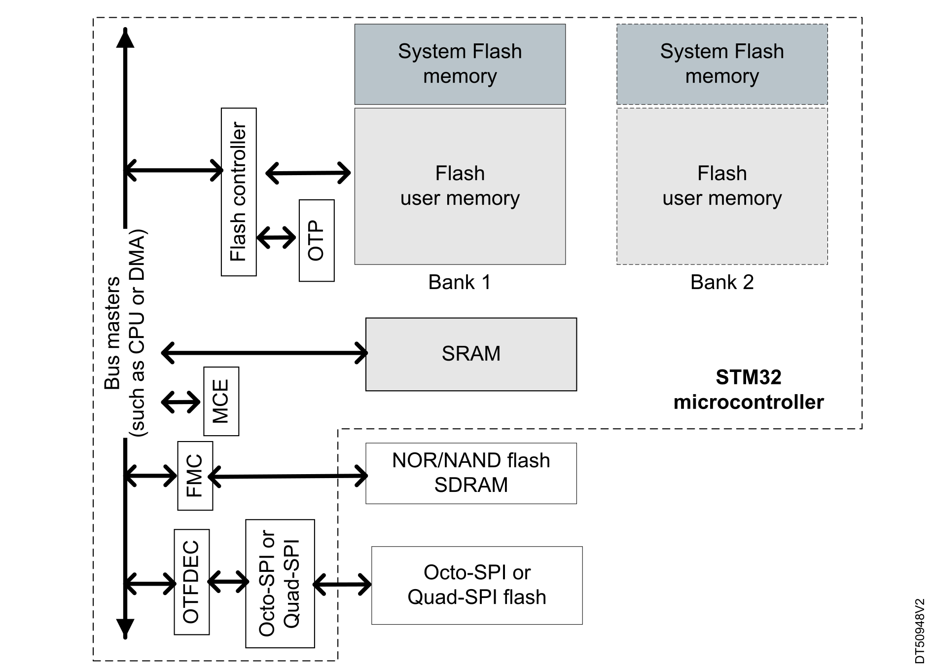
The figure below provides a simple view of memories access architecture in a microcontroller.
Figure 5. Memory types

The table below summarizes the particularities of each type of memories and typical protection features.

Table 5. Memory types and associated protection
MemoryTypesDescriptionProtections
System flash memory
  • Internal
ROM part of the flash memory. Embeds device bootloader and other ST services.Cannot be updated (erase/written).

A part may also be unreadable.

User flash memory
  • Internal
Flash memory for user applicationInternal protections:
  • RDP
  • WRP
  • TrustZone
  • PCROP (not for SRAM)
  • OTP (not in SRAM)
  • Firewall
  • Secure hide protection (not for SRAM)
  • MPU
SRAM
  • Internal
Working memory for stack, heap or buffers. Can be used to execute the firmware downloaded from internal or external non-volatile memories.
NAND, NOR, octo‑SPI, or quad‑SPI flash memory
  • External
Additional memory for applications or data storage
  • Cryptography (MCE, OTFDEC)
SDRAM
  • External
Additional RAM for application executionCryptography (MCE)

System flash memory

In STM32 MCUs, the system memory is a read-only part (ROM) of the embedded flash memory. It is dedicated to the ST bootloader. Some devices include the root of trust chain link of the secure boot and additional root secure services (RSS) in this area. This part cannot be modified to guarantee its authenticity and integrity. The bootloader is readable since it does not contain any sensitive algorithm. Some parts of the system flash memory are not accessible or execute only and cannot be read by the user.

The protection attribute on the system flash memory cannot be modified.

User flash memory

This is the main user memory, used to store firmware and non-volatile data. It is part of the embedded flash memory, and can be protected by a set of memory protection features available on all STM32 MCUs.

External attacks

The embedded flash memory is easy to protect against external attacks, unlike external flash memories. Disabling the debugging port access with RDP and the controlled access of connectivity interface provide sufficient isolation from outside.

Associated protection: RDP, or closed state to disable debug access

Internal attacks

An internal read or write access to the memory can come from a malware injected either in the device SRAM or inside an untrusted library, so that the critical code and data must only be accessible by authorized processes.

Associated protections: PCROP, MPU, firewall, secure hide protection, or TrustZone

Protecting unused memory

Write protection must always be set by default on the flash memory, even on unused area, to prevent either code modification or injection. A good practice is to fill unused memory with known values such as software interrupt (SWI) op-codes, illegal op-codes, or NOPs.

Associated protections: MPU or WRP

Error code correction (ECC)

The flash memory sometimes feature ECC that allows error detection and correction (up to 2-bit error detection and 1-bit error correction). More considered as a safety feature, it also works as a complementary protection against fault injection.

Embedded SRAM

The embedded SRAM is the device working memory. It is used for stack, heap, global buffers, and variables at runtime. The SRAM can be accessed as bytes, half-words (16 bits), or full words (32 bits), at maximum system clock frequency without wait state.

Code execution

The part of the firmware that requires faster performances can be downloaded from the user or the external flash memory, and executed from the SRAM. Another reason to execute code from the SRAM is when using encrypted external flash memory on devices without on-the-fly decryption: the code is decrypted inside the SRAM before its execution. Appropriate memory protections must then be enabled on the SRAM address range containing the code. When no code must be executed in the SRAM, it is advised to prevent any malware execution by setting the appropriate attribute (execute never) with the MPU.

Associated protections: MPU or firewall

SRAM cleaning

The SRAM can contain sensitive data or temporary values allowing some secrets retrieving. A typical example is the transfer of a secret cryptographic key from protected flash memory area in clear text, inside the SRAM. It is highly recommended to clean explicitly the working buffers and variables immediately after the processing of functions manipulating sensitive data.

Note:

In case of reset, the STM32 MCUs allow the automatic erase of the SRAM (refer to the reference manual). For some devices, part of the SRAM is protected against external access or untrusted boot (SRAM boot) when the RDP is set.

Write protection

The write protection can be used to isolate part of the area from being corrupted by another process or by preventing an overflow attack. An overflow attack consists in writing more data than the targeted buffer size (during a data transfer through interface ports for example). If no boundary checks are performed, the memory address above the buffer is corrupted, and a malware can be injected this way. This protection is only featured by the SRAM regions, which are used primarily for code execution (this protection is not practical for data). The SRAM write protection is available for SRAM2 region on some STM32 MCUs only (refer to Overview of security features and to the reference manual).

Associated protections: MPU, TrustZone, or SRAM write protection (available on some STM32 devices only)

Parity check and ECC

The parity check on the SRAM allows the control of potential errors word-by-word (32 bits). One extra bit per byte is added to the memory content (data bus width is 36 bits) to increase its robustness, as required for instance by Class B or SIL norms. ECC is more sophisticated, with SECDED functionality, but only available for SRAM on certain MCU devices. Integrity protections based on redundancy often cannot be disabled.

External flash memories

The external flash memories are connected to the microcontroller through dedicated interfaces (NAND, NOR, Octo-SPI, or Quad-SPI). As the embedded flash memory, the external ones contain code and data, but the external storage raises the problem of confidentiality (content protection) and authentication (device protection). The hardware protection is limited to a write lock, to avoid content erasing or modification. Further protection is brought by cryptography algorithms. The content must be at least signed to avoid execution of unauthenticated firmware. Encryption is required only if the content is confidential.

The embedded code can be either executed in-place or loaded into the SRAM before execution. Execution in-place of encrypted firmware is possible only if the device has on-the-fly decryption capabilities. In the other case, the firmware must be decrypted when loaded into SRAM. If the decrypted code or parts of it are not protected from readout (RDP2), then the confidentiality of the code is violated. It is also recommended to combine encryption with integrity protection.

Associated protection: OTFDEC, MCE

STM32 memory protections

Several STM32 features are available to cover the various cases considered. They are listed in the table below with their respective scope, and described in STM32 security features.
Table 6. Scope of STM32 embedded memory protection features
FeatureExternal attack protectionInternal attack protectionFlash memorySRAM
RDP, life cycleYesNoYesYes
FirewallNoYesYesYes
MPUNoYesYesYes
PCROP1YesYes (read/write)YesNo
WRP2YesYesYesNo
HDPYesYesYesYes (for execution)3
TrustZone®, RIFYesYesYesYes
1 Support of this feature in Armv6-M products is limited as constant data cannot be stored in NVM.
2 Write protection can be unset when RDP level ≠ 2.
3 The SRAM is protected by a secure area only at secure code execution. It must be cleaned before leaving the secure area.