Thermal systems definitions and basic concepts
This section details basic definitions and concepts related to thermal systems, as applied to silicon-based integrated circuits (ICs).
This section details basic definitions and concepts related to thermal systems, as applied to silicon-based integrated circuits (ICs).
Heat:
The amount of energy exchanged between two different bodies spontaneously under the effect of their different temperatures.
Temperature:
A comparative measurement of how hot or cold a body is. The temperature of a given body increases as it absorbs heat and decreases as it releases heat.
Temperature gradient:
Refer to the uneven temperature distribution over one body. The temperature gradient magnitude reflects the difference in temperature from one location to another inside a body.
Thermal resistance:
The property of a material to conduct a certain amount of heat under a certain temperature gradient.
Thermal systems are designed with complex thermal models and advanced simulation software tools. These models and tools are used to obtain accurate results.
To resolve a thermal system with an acceptable accuracy and with limited computation effort, many simplifying hypotheses can be used (such as considering the thermal resistance to be temperature independent). Using these hypotheses, the study of thermal systems is analogous to the study of electrical systems, where the heat is equivalent to the electrical current, the temperature is equivalent to the voltage, and the thermal resistance is equivalent to the electrical resistance.
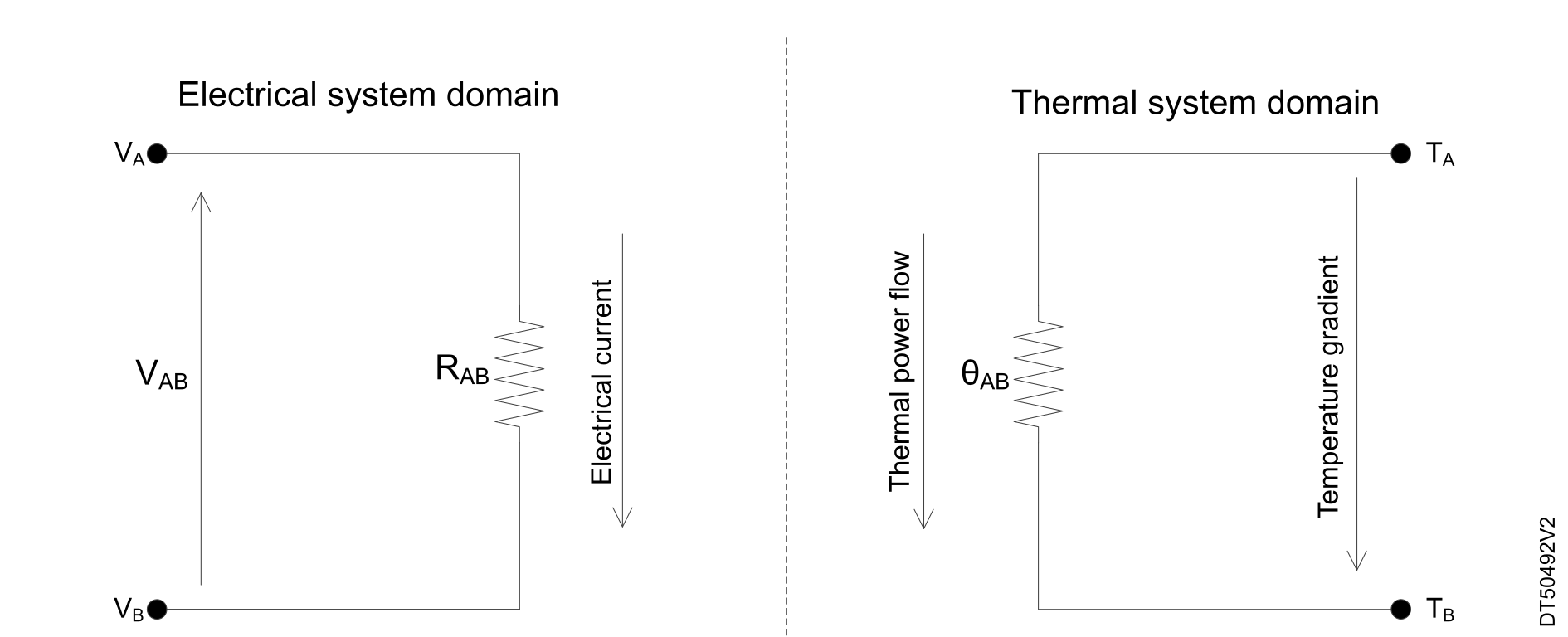
This model is widely accepted by the electronic industry. Most semiconductor vendors provide thermal resistance parameters of their packaged products based on this simplified model, in accordance with certain standardization bodies (like JEDEC EIA/JESD 51‑X standards). Designers consider the provided thermal resistance parameters when dealing with heat dissipation in their application, or at least, at an earlier stage, when selecting the right package for a given product.
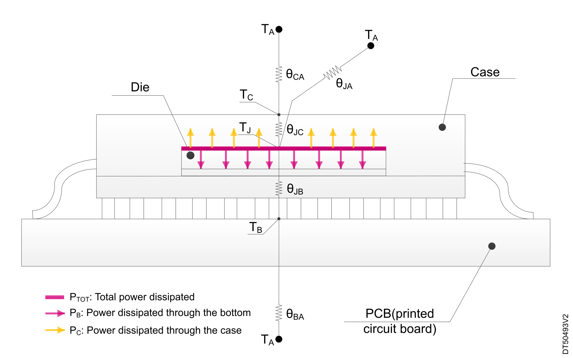
| Symbol | Description | Unit |
|---|---|---|
| TJ | Temperature of the die | °C |
| TA | Temperature of surrounding air | |
| TC | Temperature of the package top | |
| TB | Temperature of the board near the device | |
| θJC | Thermal resistance between the die and the package | °C/W |
| θJB | Thermal resistance between the die and the PCB on which the IC is mounted | |
| θJA | Thermal resistance between the die and the air surrounding the die package | |
| PB | Amount of power dissipated by the device through the board | W |
| PC | Amount of power dissipated by the device through the package top | |
| PTOT | The total power dissipated by the device (PTOT = PB + PC) |
This section explains the STM32 thermal parameters as specified by their respective datasheets.
In the electronic field, there is no consensus about a standard and unified definition of the ambient temperature. What is sure is that the ambient temperature is the temperature of the device surroundings, but there are many different ways to measure it. Measurement parameters such as the distance between the measurement point and the device, if the surrounding air is steady or not, the volume of the test environment, can severely impact later interpretation of the results.
JEDEC provides a standard definition for ambient temperature but that definition is limited to the JEDEC test environment used when determining package thermal characteristics.
Most of the time, the application operating conditions differ significantly from the JEDEC environment, making the JEDEC defined thermal resistance from junction-to-ambient temperature (Θ-JA) not practically usable for high-performance high-power-dissipation devices.
The junction temperature is the widely used term to refer to the temperature of a die. Obviously, the die temperature is the most important temperature to consider for a device, as all its electrical parameters depend on this junction temperature. Indeed, the junction temperature is the one considered when qualifying the reliability of a device.
In theory, the die temperature is not uniformly distributed across the die. There is a temperature gradient across the die. In practice, the die temperature is generally considered to be uniformly distributed, and only a single temperature measurement is provided. This reduction of a temperature gradient into one temperature reading introduces a small uncertainty into subsequent assumptions and computations when the die dimensions are relatively small. This is the case for most STM32 devices.
Both the ambient and the junction temperatures specify the thermal performance of STM32 devices.
For many STM32 devices, only the maximum ambient temperature is specified as their thermal performance limit. The junction temperature is also sometimes added.
The use of the ambient temperature for thermal performance assessment is much easier than using the junction temperature, as the die of a packaged device is not accessible. This makes the conventional temperature measurement methods unusable for measuring the die temperature.
Measuring the junction temperature requires more advanced measurement techniques. Most STM32 devices embed a junction temperature sensor, which serves as a primitive building block for thermal watchdog implementations. But at the design stage, this embedded temperature sensor cannot help in determining the thermal performance of the whole application. Instead, the junction temperature is estimated at the design stage. It is based on many parameters including the application power profile, the device thermal resistances, the surrounding temperature (board temperature and device case temperature). For accurate estimation of the junction temperature, modeling software tools are used when the final application has a complex thermal model and a complex power profile.
The case temperature is the temperature of the top of the package used as a chip carrier for the die. The JEDEC standards specify that the temperature sensor must be placed at the center of the package top, using 1 mm of conductive epoxy.
If the package case-to-ambient thermal resistance is much higher than the package junction-to-case thermal resistance (one order of magnitude at least), and as most devices dissipated power goes through the board, the junction temperature can be conflated with case temperature if some uncertainty is acceptable.
The board temperature, as defined by the JEDEC standards, is the PWB temperature measured near the center lead of the longest side of the device. The board temperature and the package junction-to-board thermal resistance are very critical parameters when assessing the device thermal performance.
Under steady air conditions, most of the heat generated by the device is dissipated through the board. The heat dissipated through the board can be 20 times higher than the heat dissipated through the package top. For instance, for a JEDEC high-conductivity test board and under steady air conditions, 95% of the device power dissipation passes through the board and only 5% is dissipated through the package top.
| Thermal metric | Symbol | Value | Main purpose |
|---|---|---|---|
| Theta‑JA | θJA |
|
Used to rank package performance in the JEDEC environment |
| Theta‑JC | θJC |
|
Used to rank package performance Used in simulations with a 2R model (2R = two resistances) |
| Theta‑JB | θJB |
|
Used to rank package performance Used in simulations with 2R model |
These thermal resistances must be carefully defined in semiconductor packages and devices context.
There are no extraneous parallel thermal paths in the system allowing some of the heat to “leak” away. All the heat leaving the junction eventually arrives at or passes through the other point.
It is usually possible to know the total power dissipation of a device but it is far more difficult to know which fraction of the heat flows out through the case top, versus the part that flows through the leads, and versus the part that flows through the air gap under the package.
Theta‑JC and Theta‑JB are generally used as inputs for thermal simulation tools, which calculate which fraction of the heat flows out through the top and the bottom of the device.