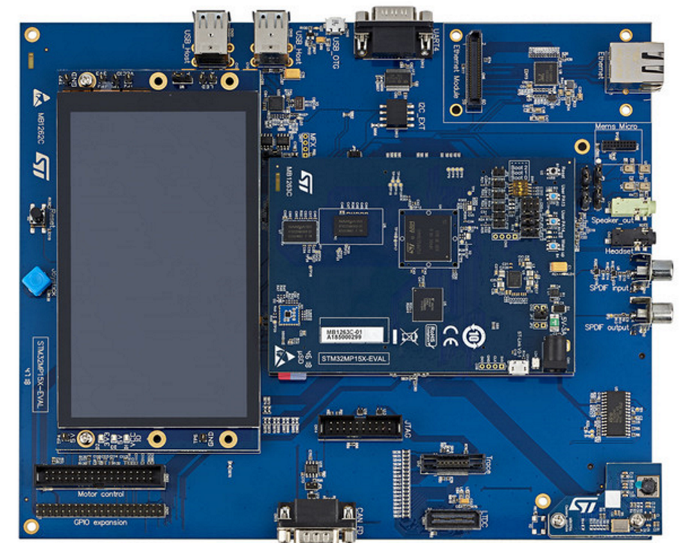
This thermal analysis has been done on an evaluation board with an STM32MP157 device, without casing (see the figure below).
Figure 15. STM32MP157x-EV1. This picture is not contractual.
While running commands, the script monitors the following:
The CPU load with mpstat
The board temperature via / sys / class / hwmon / hwmon0 / temp1_input
The memory used via the free command
STM32MP157 power dissipation
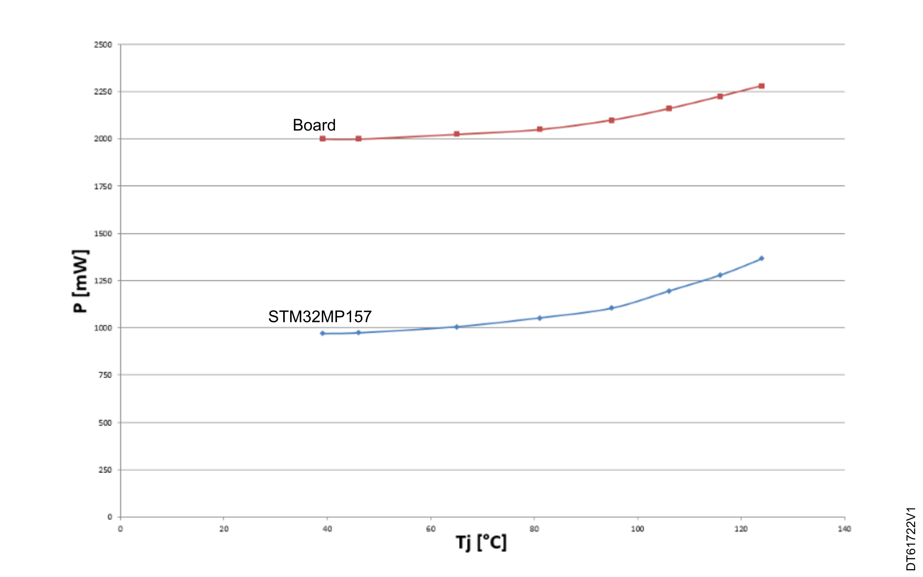
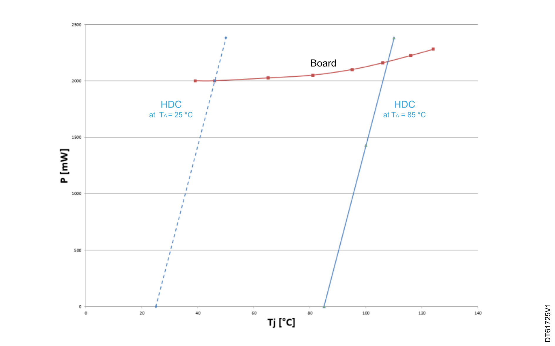
As stated in STM32 thermal parameters, the dissipated power varies with TJ. The power consumption in this example is measured for different TJ values (see the table and the figure below).
Table 7. STM32MP157 power dissipation versus TJ
TJ (°C)
STM32MP157x-EV1 board (supplied with 5 V)
STM32MP157 power dissipation (mW)
Current consumption (A)
Power consumption (mW)
39
0.4
2000
970.2
46
0.4
2000
973.8
65
0.405
2025
1006.4
81
0.41
2050
1053.1
95
0.42
2100
1104.7
106
0.432
2160
1195.5
116
0.445
2225
1280.6
125
0.456
2280
1366.6
Figure 16. Junction-temperature-dependent dissipated power for STM32MP157
STM32MP157 thermal measurements at TA = 25 °C
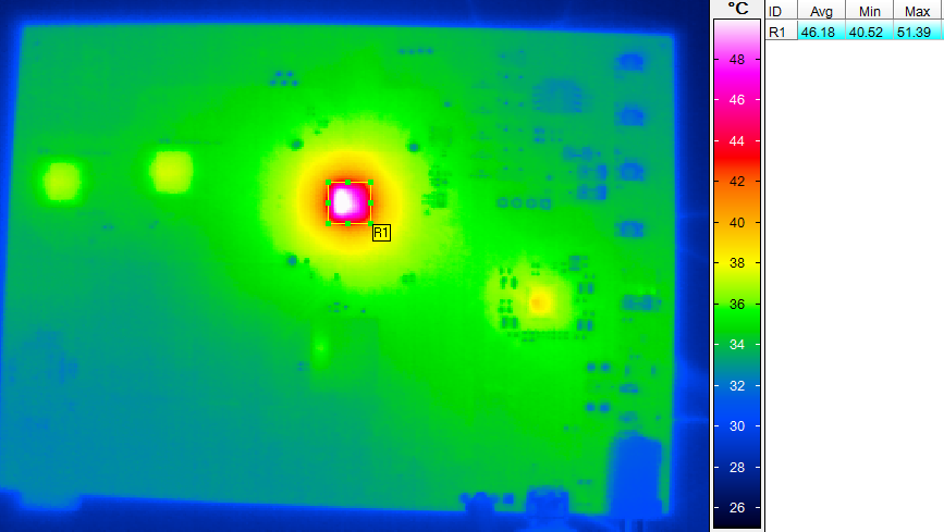
The figures and table below detail the thermal measurements performed at TA = 25 °C.
Figure 17. STM32MP157 thermal measurements at TA = 25 °C
Table 8. STM32MP157 thermal measurements at TA = 25 °C
TJ (°C)
Thermal camera measurement (°C)
STM32MP157 power consumption (mW)
Total power consumption (mW)
Avg
Min
Max
46
46.2
40.52
51.4
974
2000
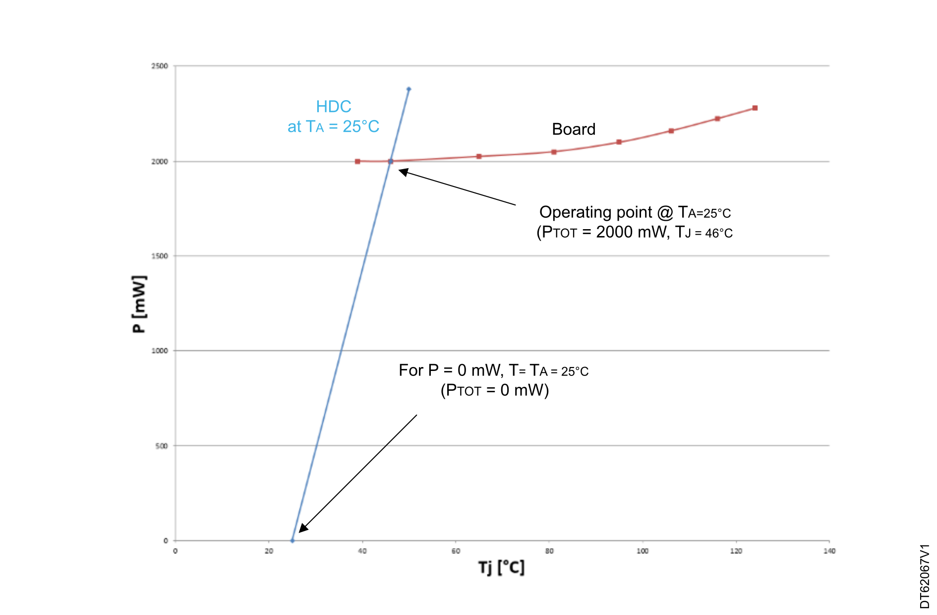
Figure 18. HDC at 25 °C and junction-temperature-dependent dissipated power for STM32MP157
Once the HDC of the design is defined (by measurement at 25 °C), and assuming that this HDC is constant at 25 °C and 85 °C, the operating point of the design at 85 °C is given by translating the HDC at 85 °C as shown in the figure and table below.
Figure 19. HDC at 85 °C and junction-temperature-dependent dissipated power for STM32MP157
Table 9. Measurement interpolation at TA = 85 °C for STM32MP157
Parameter
Value
TJ
110 °C
PTOT
2200 mW
In conclusion, the STM32MP157 device is safe, with no thermal runaway, and TJ remaining < 125 °C.
Internal validation board with STM32MP135 MPU
This thermal analysis has been done on an internal validation board with an STM32MP135 device without casing.
This analysis is based on the use cases detailed in the table below. They correspond to CPU frequencies of 900 MHz and 1 GHz:
Table 10. Use cases for STM32MP135 MPU
Name
Description
CPU load
DDR load
cpuburn
-
100%
R = 3 Mbyte/s, W = 0 Mbyte/s, R&W = 4 Mbyte/s
dd
Idle (weston launcher, netdata) + dual eth + USB hard drive + dd on hard drive (ETH cables unplugged)
R = 129 Mbyte/s, W = 40 Mbyte/s, R&W = 169 Mbyte/s
STM32MP135 power dissipation
Use case about cpuburn
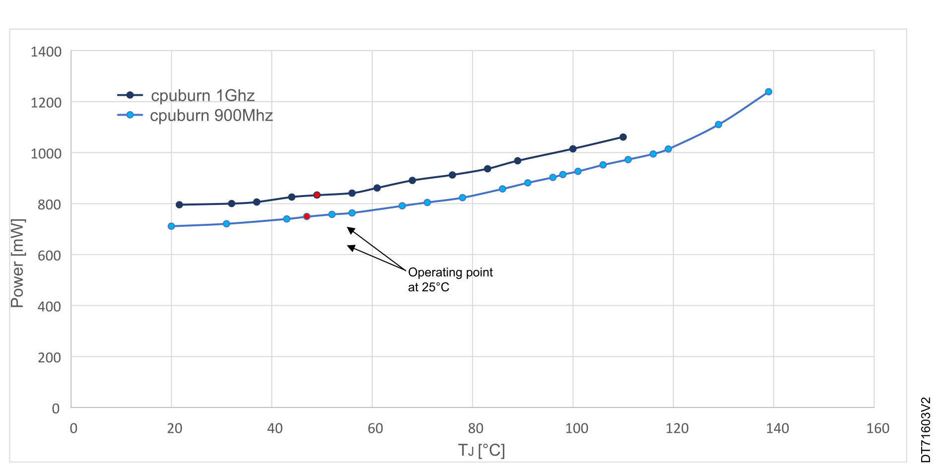
As stated in STM32 thermal parameters, the dissipated power varies with TJ. The power consumption in this example is measured for different TJ values (see the following tables and figure).
Table 11. STM32MP135 power dissipation versus TJ at 900 MHz (cpuburn)
TJ (°C)
STM32MP135 power dissipation (mW) at 900 MHz
20.00
711.44
31.00
721.04
43.00
740.00
47.00
748.83
52.00
757.93
56.00
763.62
66.00
791.42
71.00
804.79
78.00
823.36
86.00
857.92
91.00
881.62
96.00
903.01
98.00
914.23
101.00
926.44
106.00
951.83
111.00
973.00
116.00
994.98
119.00
1014.19
129.00
1110.12
139.00
1238.89
Table 12. STM32MP135 power dissipation versus TJ at 1 GHz (cpuburn)
TJ (°C)
STM32MP135 power dissipation (mW) at 1 GHz
21.60
795.45
32.00
800.12
37.00
806.26
44.00
825.79
49.00
833.00
56.00
841.39
61.00
861.53
68.00
890.82
76.00
912.60
83.00
936.60
89.00
967.97
100.00
1014.80
110.00
1061.20
Table 13. STM32MP135 thermal measurements at TA = 25 °C (cpuburn)
Parameter
900 MHz
1 GHz
Unit
TJ
47
49
[°C]
VCORE
1.32
1.332
[V]
ICORE
180
195
[mA]
PCORE
237
260
[mW]
VDD
3.33
3.321
[V]
IDD
13
19
[mA]
PDD
43
63
[mW]
VCPU
1.415
1.414
[V]
ICPU
306
331
[mA]
PCPU
432
468
[mW]
VDDR2
1.2
1.206
[V]
IDDR2
30
35.5
[mA]
PDDR2
36
43
[mW]
STM32MP135 power dissipation
748
834
[mW]
+11%
Figure 20. Junction temperature-dependent dissipated power for STM32MP135 (cpuburn)
Use case about dd
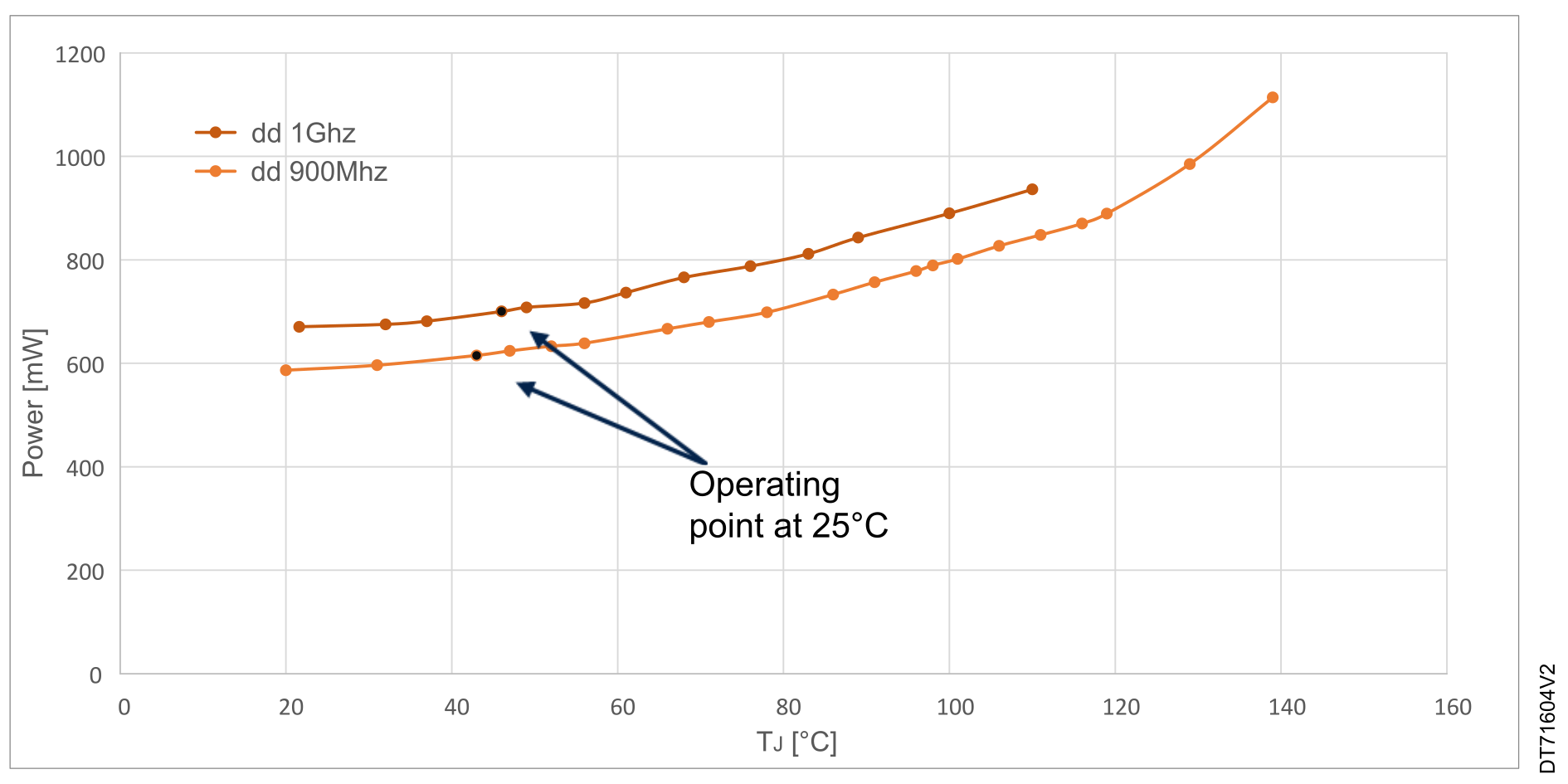
As stated in STM32 thermal parameters, the dissipated power varies with the TJ. The power consumption in this example is measured for different TJ values (see the following tables and figure).
Table 14. STM32MP135 power dissipation versus TJ at 900 MHz (dd)
TJ (°C)
STM32MP135 power dissipation (mW) at 900 MHz
20
586.44
31
596.04
43
615.00
47
623.83
52
632.93
56
638.62
66
666.42
71
679.79
78
698.36
86
732.92
91
756.62
96
778.01
98
789.23
101
801.44
106
826.83
111
848.00
116
869.98
119
889.19
129
985.12
Table 15. STM32MP135 power dissipation versus TJ at 1 GHz (dd)
TJ (°C)
STM32MP135 power dissipation (mW) at 1 GHz
21.6
670.45
32
675.12
37
681.26
46
700
49
708.00
56
716.39
61
736.53
68
765.82
76
787.60
83
811.60
89
842.97
100
889.80
110
936.20
Table 16. STM32MP135 thermal measurements at TA = 25 °C (dd)
Parameter
900 MHz
1 GHz
Unit
TJ
43
46
[°C]
VCORE
1.32
1.32
[V]
ICORE
177
198
[mA]
PCORE
233
261
[mW]
VDD
3.33
3.33
[V]
IDD
13
19
[mA]
PDD
43
63
[mW]
VCPU
1.415
1.398
[V]
ICPU
173
199
[mA]
PCPU
244
278
[mW]
VDDR2
1.268
1.268
[V]
IDDR2
75
77
[mA]
PDDR2
95
97
[mW]
STM32MP135
615
700
[mW]
+ 13%
Figure 21. Junction temperature-dependent dissipated power for STM32MP135 (dd)
HDC at 25 °C and junction temperature
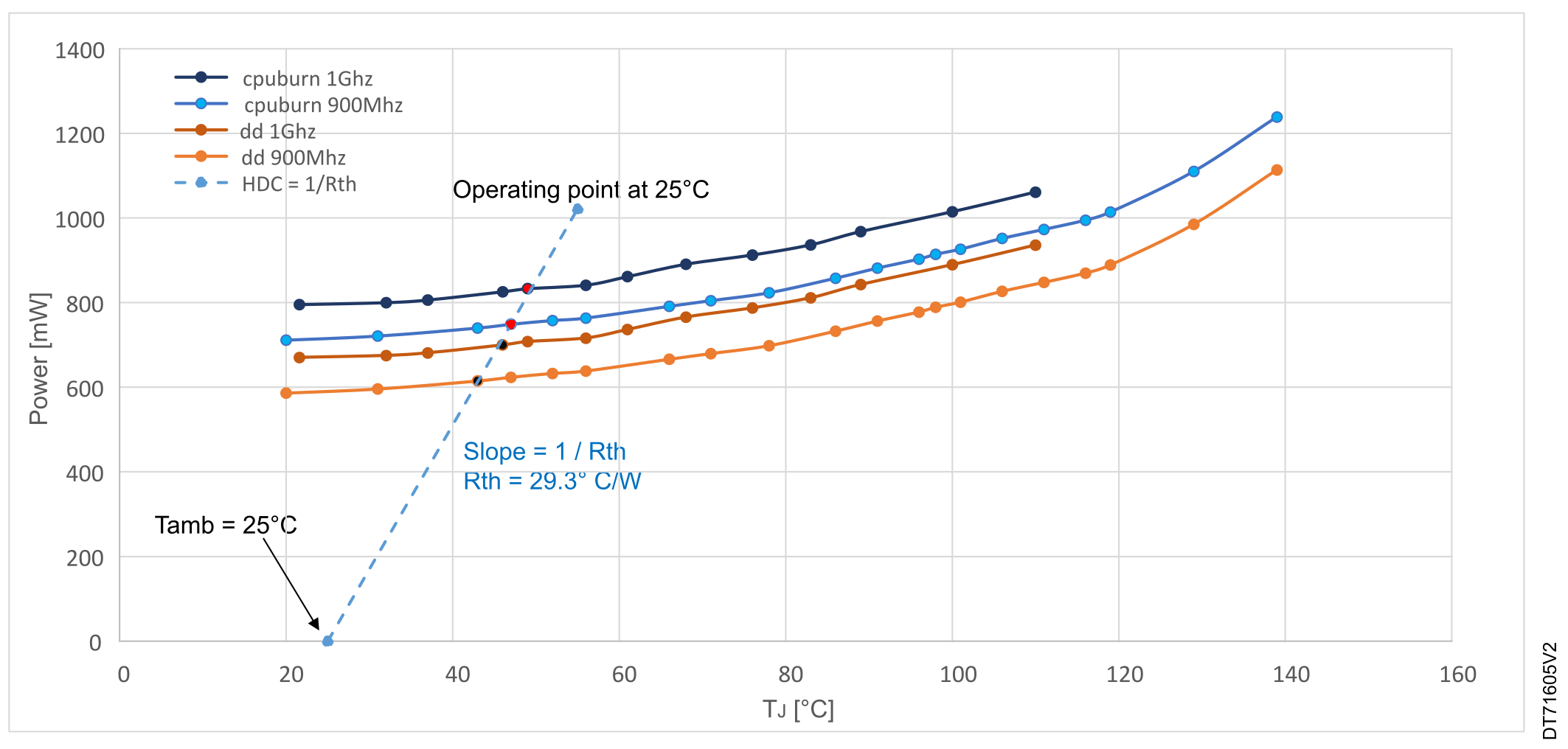
Once the design HDC is defined (by measurement at 25 °C), and assuming that this HDC is constant at 25 °C and 85 °C, the operating point of the design at 85 °C is given by translating the HDC at 85 °C as shown in the figure below.
Figure 22. MPU power dissipation
Maximum ambient temperature (STM32MP135 MPU)
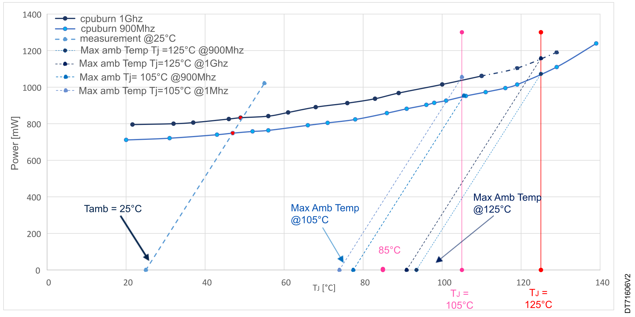
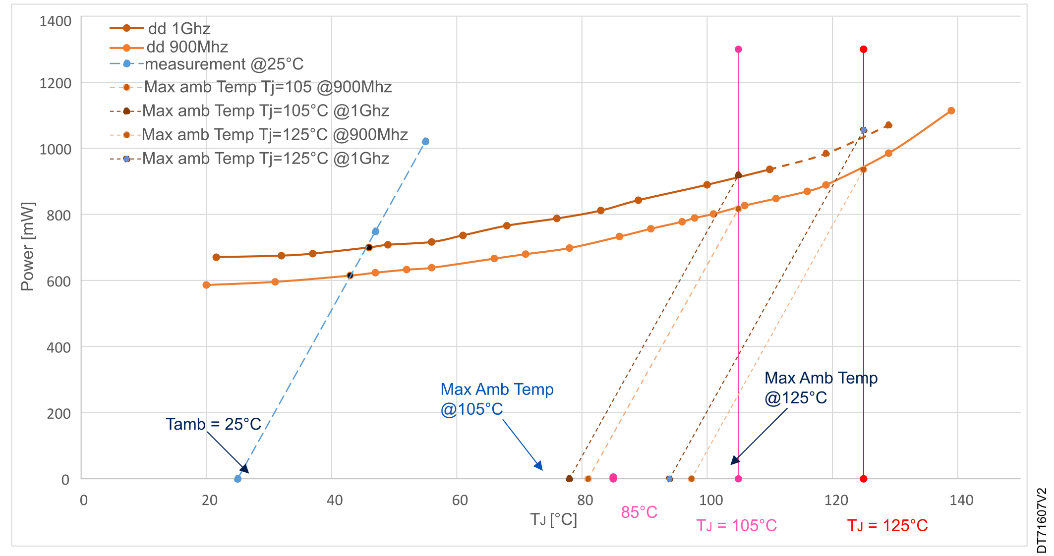
The maximum ambient temperature for the cpuburn and dd use cases are given in the figures below.
Figure 23. Maximum ambient temperature(Cpuburn)
Figure 24. Maximum ambient temperature (dd)
Conclusion
The measurement details given in the previous sections give:
An 11% and 13% increase of the power consumption between 900 MHz and 1 GHz. These are respectively for the cpuburn and dd use cases.
A 2 and 3 °C increase of TJ between 900 MHz and 1 GHz (for cpuburn and dd use case respectively)