AN5036 · Application noteGuidelines for thermal management on STM32 MCUs and MPUs
Download .pdfOpen in the full document

Internal validation board with STM32MP257 MPU

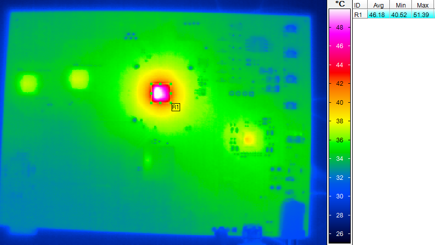
STM32MP257 thermal measurements at TA = 25 °C

The figures and table below detail the thermal measurements performed at TA = 25 °C.

Figure 26. STM32MP257 thermal measurements at TA = 25 °C


Table 18. STM32MP257 thermal measurements at TA = 25 °C
TJ (°C)Thermal camera module measurement (°C)STM32MP257 power consumption (mW)
AvgMinMax
47.5 140.2431.548.72164.77

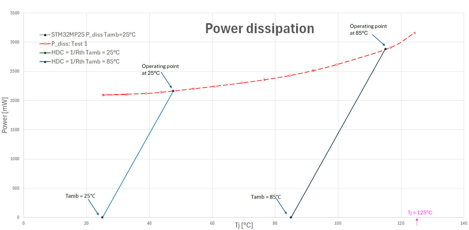
Once the HDC of the design is defined (by measurement at 25 °C), and assuming that this HDC is constant at 25 °C and 85 °C, the operating point of the design at 85 °C is given by translating the HDC at 85 °C as shown in Figure 27 HDC at 85 °C and junction temperature-dependent dissipated power for STM32MP257 and Table 19 Measurement interpolation at T A = 85 °C for STM32MP257.

Figure 27. HDC at 85 °C and junction temperature-dependent dissipated power for STM32MP257


Table 19. Measurement interpolation at TA = 85 °C for STM32MP257
ParameterValue
TJ115 °C
PTOT2886.5 mW

In conclusion, the STM32MP257 device is safe, with no thermal runaway, and TJ remaining < 125 °C.

1 Thermocouple measurement

Discovery kit with STM32N657XOH3 MCU

This thermal analysis was done on a Discovery kit with an STM32N657XOH3 device without casing.

The test case is the following:
  • Internal VDD_core
  • voshigh-trusted.bin configuration
  • CPU frequency = 800 MHz
  • NPU frequency = 1000 MHz
  • NPU RAM frequency = 900 MHz
STM32N6 max load application firmware:
  • Use DCMI and VENC in YUV2 (camera board MB1723C with OV5640 sensor)
  • Use NPU inference
  • Stream video on LTDC using GPUD2 accelerator

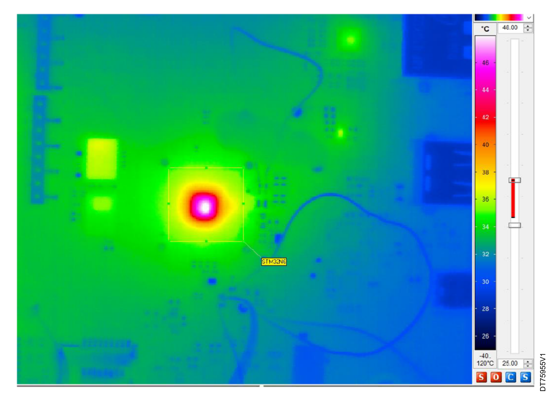
STM32N657 thermal measurements at TA = 25 °C

The figures and table below detail the thermal measurements performed at TA = 25 °C.
Figure 29. STM32N657 thermal measurements at TA = 25 °C


Table 20. STM32N657 thermal measurements at TA = 25 °C

TJ (°C)Thermal camera module measurement (°C)

Max

STM32N657 power consumption (mW)
47148.71318
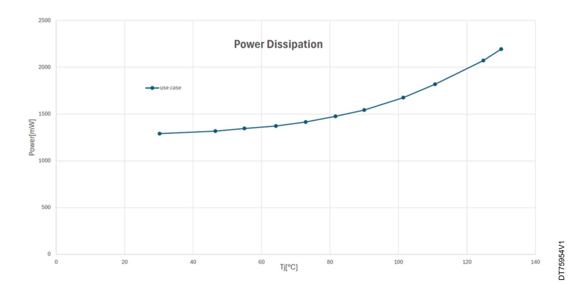
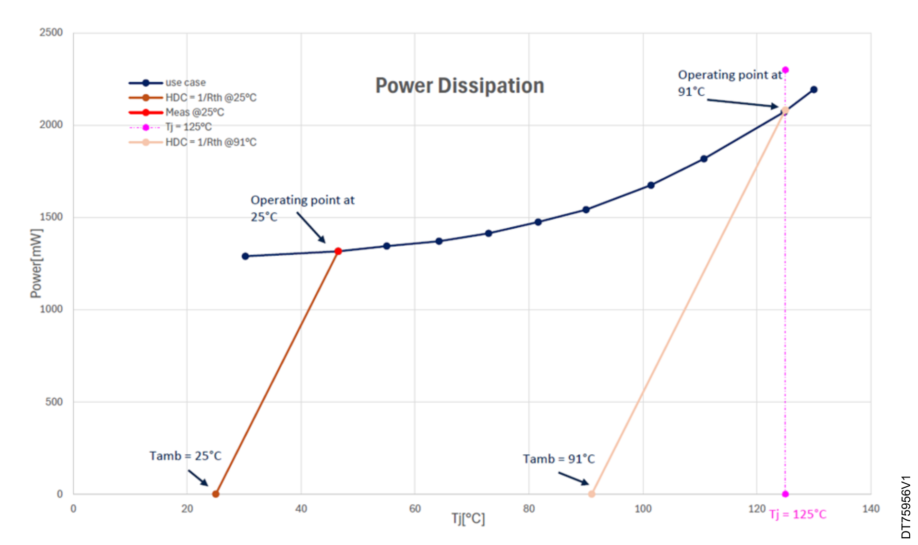
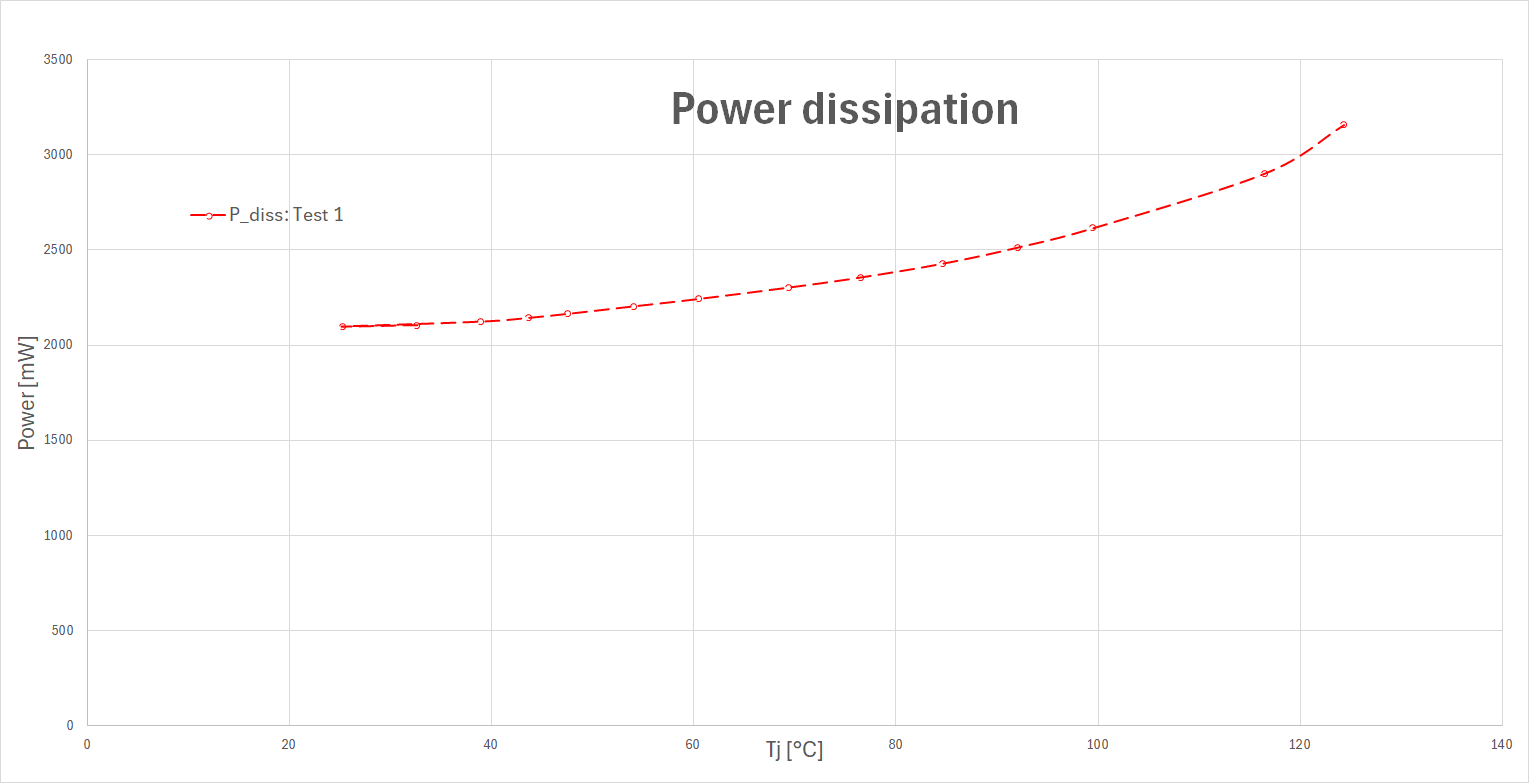
Once the heat dissipation capability (HDC) of the design has been defined (by measurement at 25 °C), and assuming that this HDC is constant at 25 °C and maximum ambient temperature, the operating point of the design at TJ = 125 °C is given by translating the HDC, as shown in the figure and table below.
Figure 30. HDC at 91 °C and junction temperature-dependent dissipated power for STM32N657


Table 21. Measurement interpolation at maximum ambient temperature for STM32N657
ParameterValue
TJ125 °C
PTOT2082 mW
Maximum ambient temperature91 °C
In conclusion, the STM32N657 device is safe, with no thermal runaway, and for TJ = 125 °C, the maximum ambient temperature TA = 91 °C.
1 Thermocouple measurement

STM32MP215F thermal measurements at TA = 25 °C

This section explains the STM32 thermal parameters as specified by their respective datasheets.

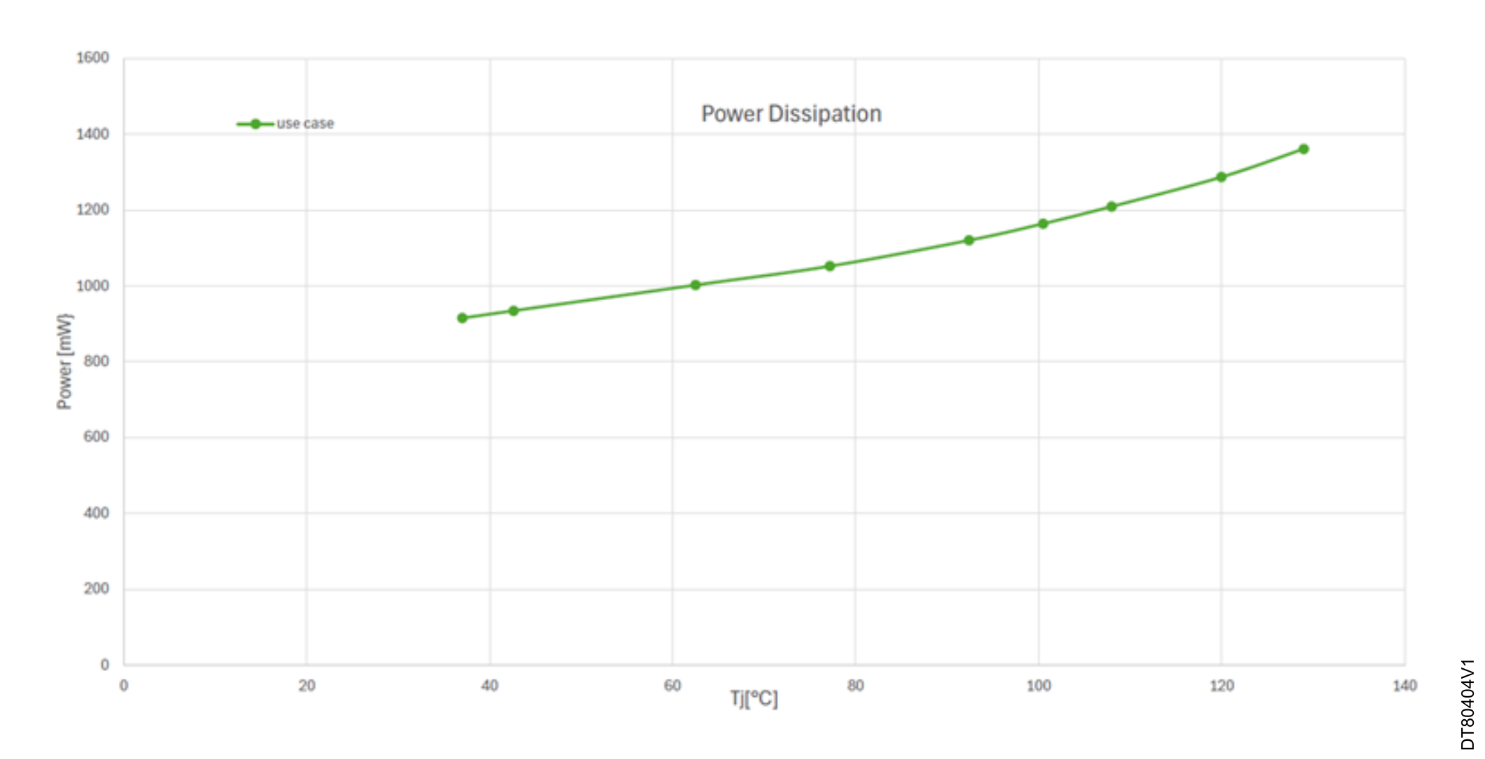
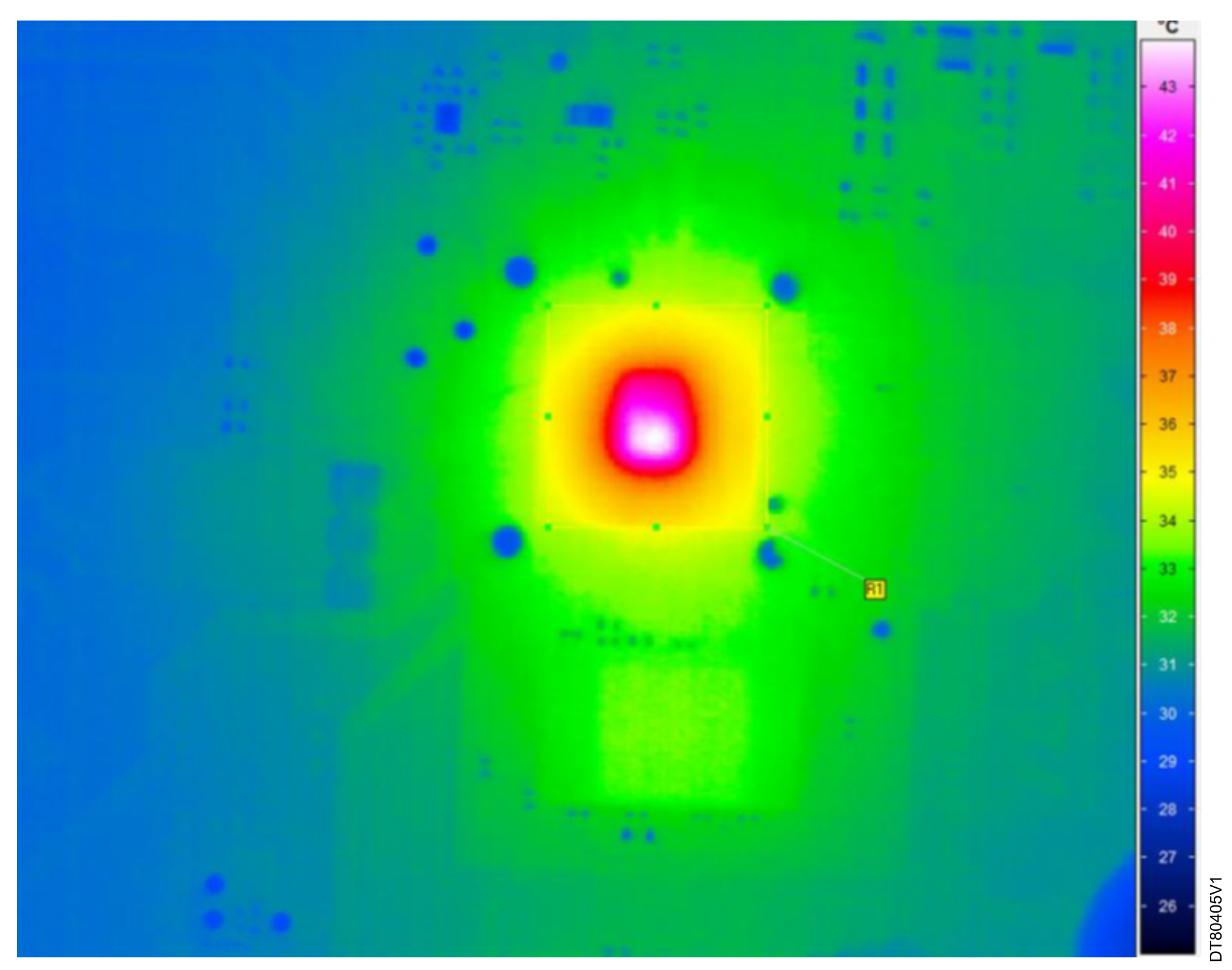
Figure and table below detail the thermal measurements performed at TA = 25 °C.

Figure 32. STM32MP215F thermal measurements at TA = 25 °C


Table 22. STM32MP215F thermal measurements at TA = 25°C

TJ (°C)IOCPUCOREDDR1V8Power (mV)
431V (V)3.319V (V)0.935V (V)0.893V (V)1.239V (V)1.814934.37
I (mA)40I (mA)160I (mA)315I (mA)226I (mA)50

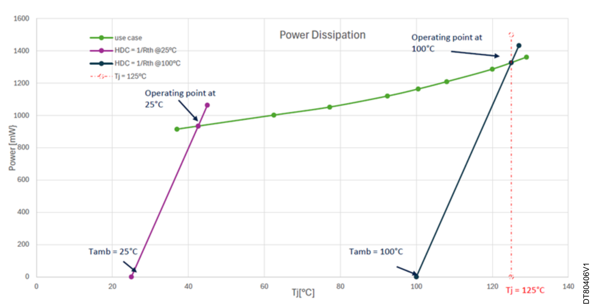
Figure and table hereafter detail the thermal measurements performed at maximum ambiant temperature TA = 100 °C.

Figure 33. HDC at 100 °C and junction temperature-dependent dissipated power for STM32MP215F


Table 23. Measurement interpolation at maximum ambient temperature for STM32MP215F
Parameter Value
TJ125 °C
PTOT1327 mW
Maximum ambient temperature100 °C

In conclusion, the STM32MP215F device is safe, with no thermal runaway, and for TJ = 125 °C, the maximum ambient temperature TA = 100 °C.

1 Thermocouple measurement