DCMIPP functional description
This section details the DCMIPP and how it handles image data and synchronization signals.
This section details the DCMIPP and how it handles image data and synchronization signals.
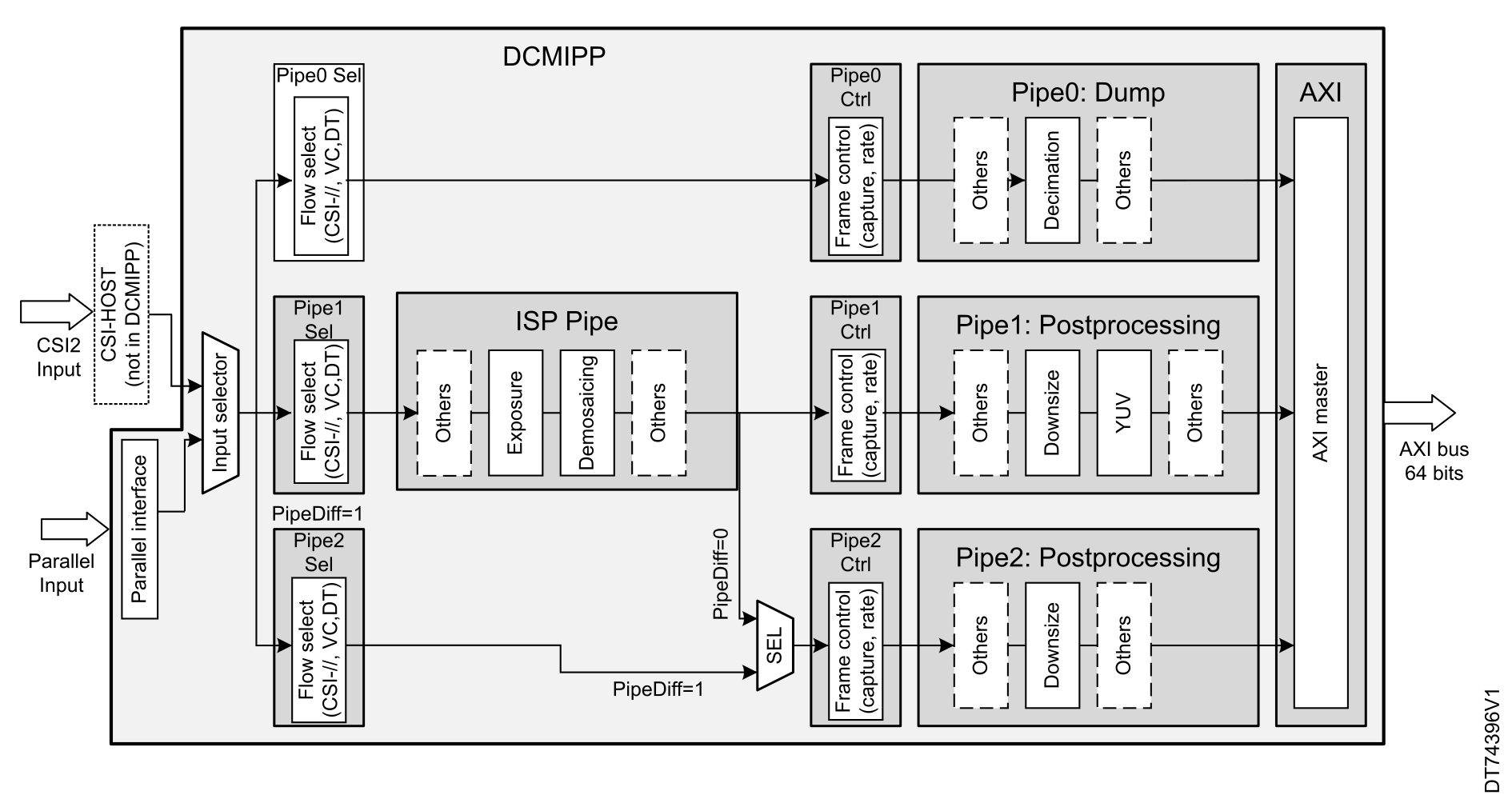
As mentioned in Figure 7 DCMIPP architecture, the DCMIPP receives pixels from either a parallel or CSI interface. Once the pixel data enters, it passes through a flow selector (FLOWSEL) that directs the data to the appropriate processing pipelines.
The architecture features three main pipelines for pixel processing:
STM32H7R3/7S3 includes only Pipe0-Dump pipeline in the DCMIPP architecture.
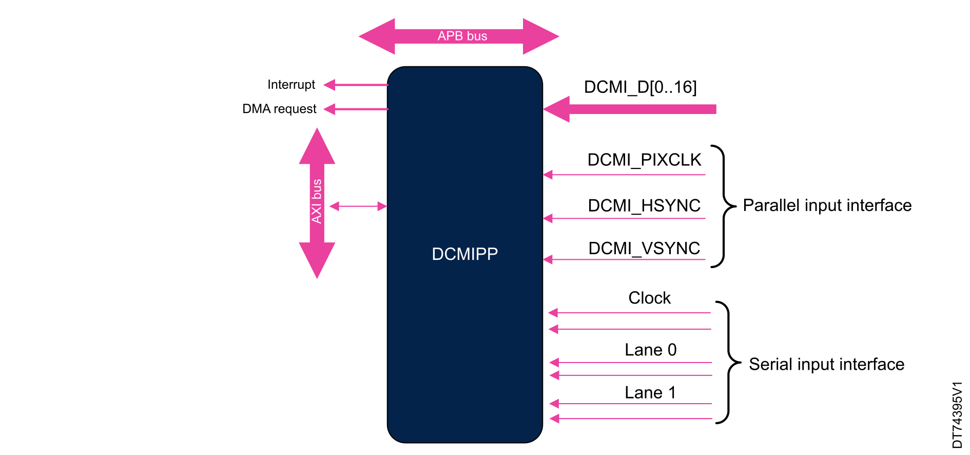
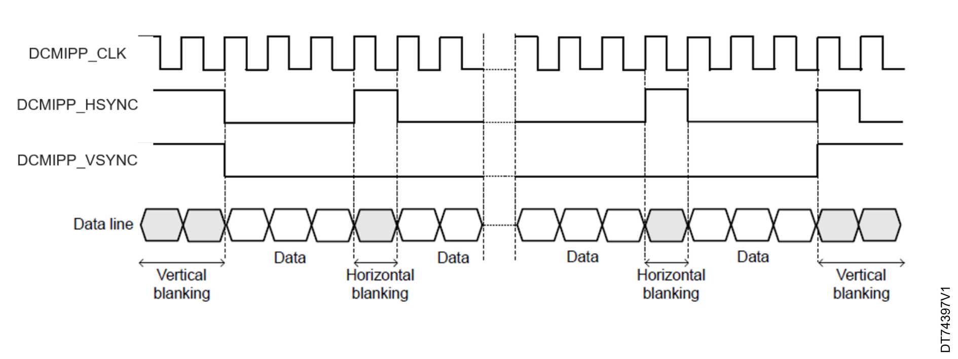
In hardware synchronization mode, the system uses two synchronization signals, DCMIPP_HSYNC and DCMIPP_VSYNC. Depending on the camera module and mode, data can be transmitted during horizontal and vertical synchronization periods. DCMIPP_HSYNC and DCMIPP_VSYNC act as blanking signals, as all data received during DCMIPP_HSYNC and DCMIPP_VSYNC active periods are ignored.
To correctly transfer images in the RAM buffer, data transfer is synchronized with the DCMIPP_HSYNC and DCMIPP_VSYNC signals.
When the hardware synchronization mode is selected and capture is enabled (CPTREQ bit set in DCMIPP_PxFCTCR), data transfer is synchronized with the deassertion of the DCMIPP_VSYNC signal (next start of frame).
Then, the transfer can be continuous, with successive frames transferred by the IP-Plug to either the same buffers, succesive buffers or circular buffers.
Figure 9 Frame structure in hardware synchronization mode illustrates an example of data transfer when DCMIPP_VSYNC and DCMIPP_HSYNC signals are active high, and when the capture edge for DCMIPP_PIXCLK is the rising edge.
The embedded data synchronization mode is available only with the parallel interface capture mode. In this mode, the data flow is synchronized using embedded 32-bit codes with the values 0x00 and 0xFF, which are no longer used in the data.
There are four types of codes, all with 0xFF0000XY format. The embedded synchronization codes are supported only in 8-bit parallel data capture (in the DCMIPP_PRCR register, the EDM[2:0] bits must be programmed to “000”). For other data widths, the synchronization mode generates unpredictable results.
Camera modules generate up to eight synchronization codes when in interleaved mode, while the DCMIPP reacts to one single code. Therefore, in an interleaved flow with an embedded synchronization, every other frame is discarded because it is not detected.
This mode is ITU656 compatible (ITU656 is the digital video protocol of ITU-R BT.656).
The following reference codes indicate a set of four events:
Figure 10 Frame structure in embedded synchronization mode 1 illustrates the frame structure using this mode.
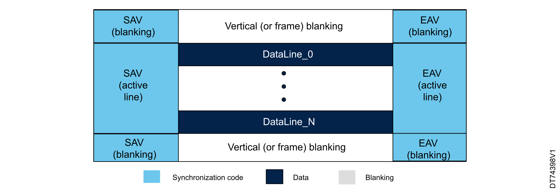
A 0xFF value programmed as a frame-end (FE) means that all the unused codes (the possible values of codes other than FS, LS, LE) are interpreted as valid FE codes.
In this mode, once the camera interface has been enabled, the frame capture starts after the first occurrence of an FE code followed by an FS code.
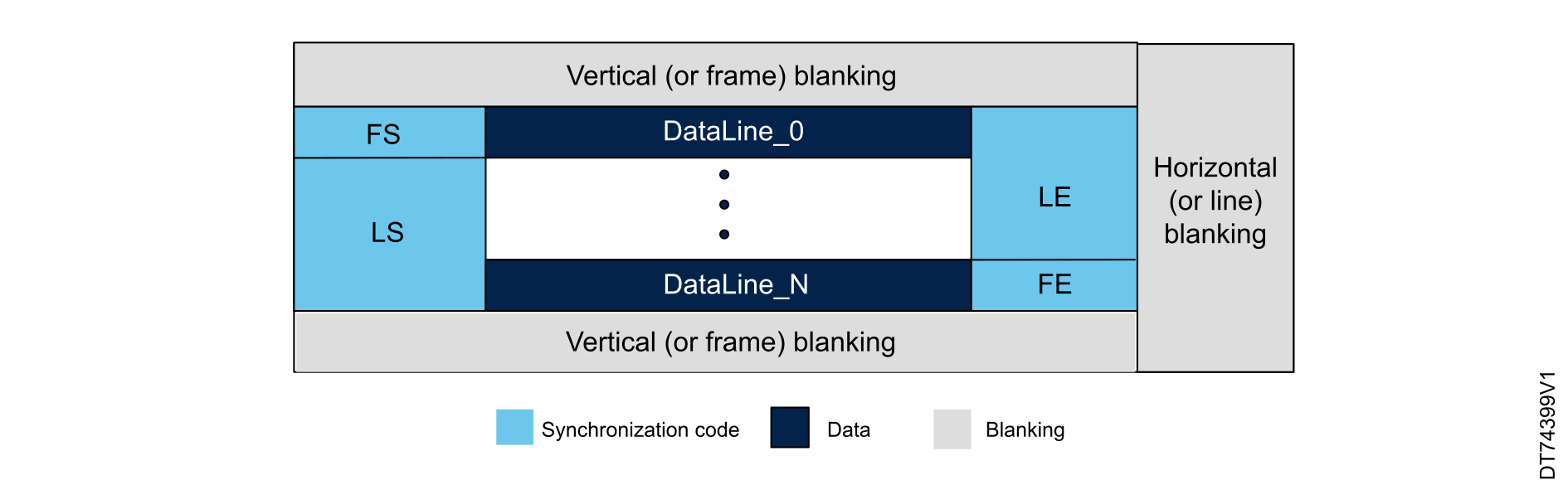
The CSI-2 low-level protocol supports the transport of arbitrary data using both short and long packet formats, with packets transmitted over the physical D-PHY interface. The protocol has the following characteristics:

As illustrated in the figure before, the sequence of the CSI-2 frames begins with an exit from the low-power state (LPS), followed by the start of transmission (SOT) signal, indicating the start of the packet.
Initially, a short packet (SP) is transmitted, followed by the end of transmission (EOT) signal, and a return to low-power state. The sequence then transitions again with SOT to transmit a long packet, which includes a packet header (PH), payload data (DATA), and a packet footer (PF) for error detection, followed by EOT and a return to low-power state. This process repeats for subsequent long packets, ensuring efficient and robust communication.
The CSI-2 low-level protocol consists of short and long packets, each with a distinct role.
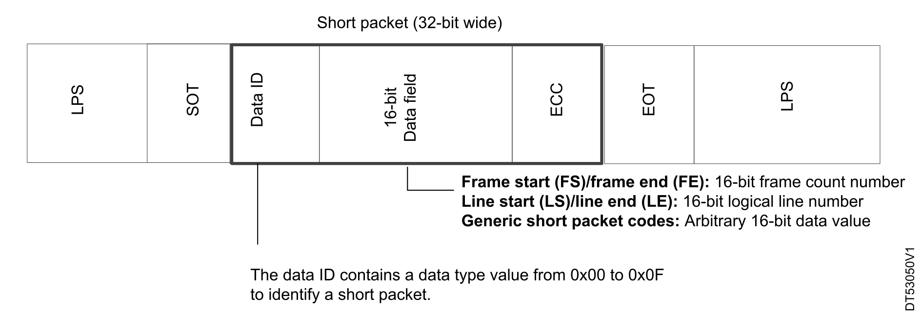
The CSI-2 short-packet format for a D-PHY physical layer is shown in the figure below .It is similar to the long packet header, except that the word count field is replaced by a 16-bit data field. The ECC 8-bit code is present to secure headers having potential bit corruption.
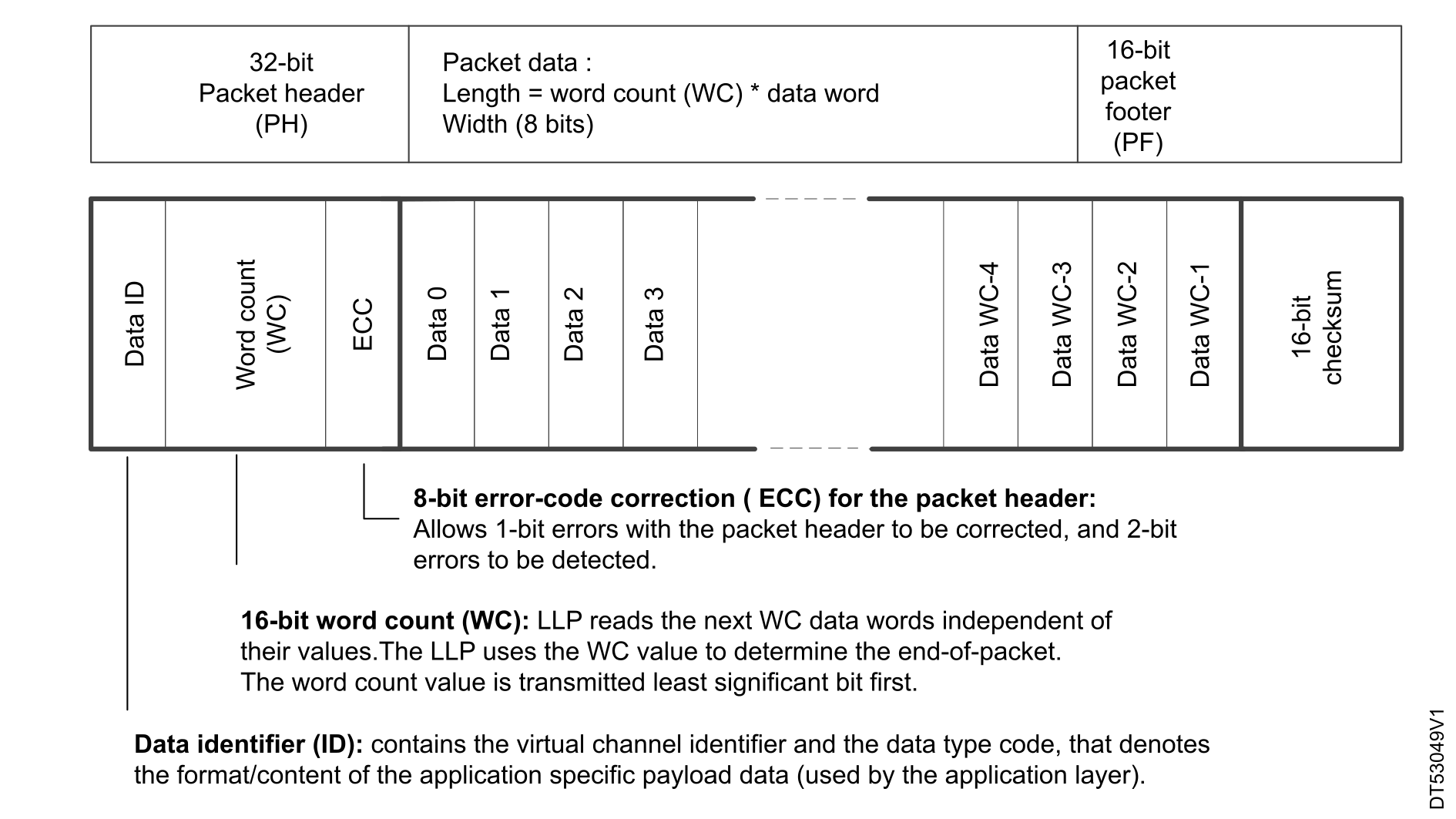
The figure below presents the long packet format. It includes a data ID that consists of a virtual channel number, associated with the data packets, and the corresponding data type.
The word-count field allows the LLP to determine the data-payload width before detecting the packet footer and the EOT. This information is used to detect shorter-than-expected packets, and to trigger a corresponding error
The ECC corrects a single erroneous bit in the packet header in the case of data corruption.
The packet data corresponds to the data payload for a given virtual channel and for an identified data type. To complete the long-packet reception block, a packet footer that contains a 16-bit CRC checksum is received and compared to that which is internally calculated by the LLP, to check the data integrity of the received data payload.
Specific to Pipe 0
Each pipe has a dedicated interrupt local register that controls the fourth interrupt event (OVR, VSYNC, FRAME, LINE), as indicated in the DCMIPP_P0SR, DCMIPP_P1SR and DCMIPP_P2SR registers for Pipe0, Pipe1, and Pipe2.
| Pipe | Event |
|---|---|
| Pipe0 | HSYNC |
| VSYNC | |
| Frame | |
| Line | |
| Pipe1 | HSYNC |
| VSYNC | |
| Frame | |
| Line | |
| Pipe2 | HSYNC |
| VSYNC | |
| Frame | |
| Line |
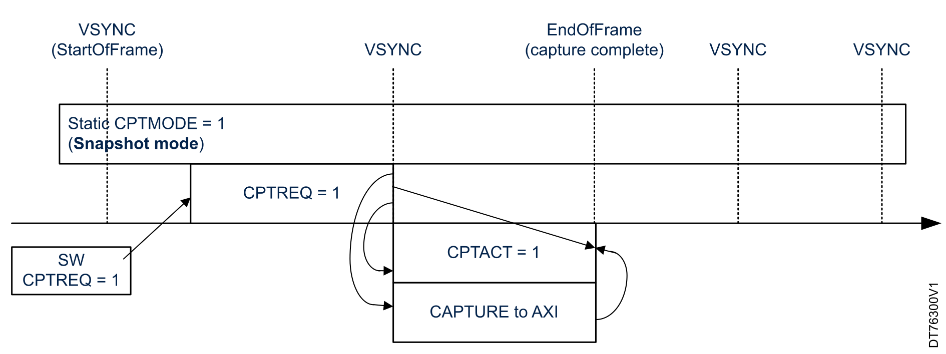
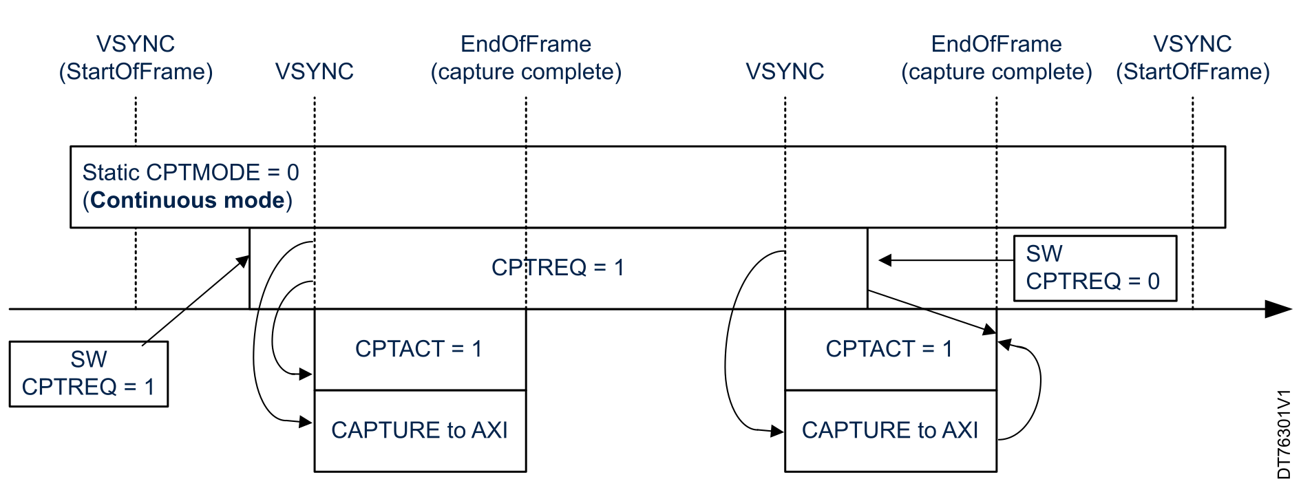
The DCMIPP captures only the frames required by the application optimizing memory access, AXI bus occupation and power consumption. The applicative software may request to get continuous frames from the camera sensor, or only frame in snapshot mode. These two different modes are selected thanks to the bit CPTMODE inside the DCMIPP_PXFSCR register.