AN6211 · Application noteIntroduction to digital camera interface pixel pipeline for STM32 MCUs
Download .pdfOpen in the full document

Configuration for JPEG sensors

Configuration for JPEG sensors

To capture a JPEG-compressed stream from a JPEG sensor via the parallel or CSI-2 interfaces, the user must use Pipe0 by enabling the modules highlighted in Figure 37 Capturing JPEG pixels using Pipe0. When selecting a parallel interface, the DCMIPP Pipe0 should be configured with byte pixel format, with swap cycles disabled, and hardware synchronization enabled.

Using the CSI-2 camera sensor, the user needs to configure the virtual channel and data types to JPEG byte stream mode for Pipe0 via the flow selection module.
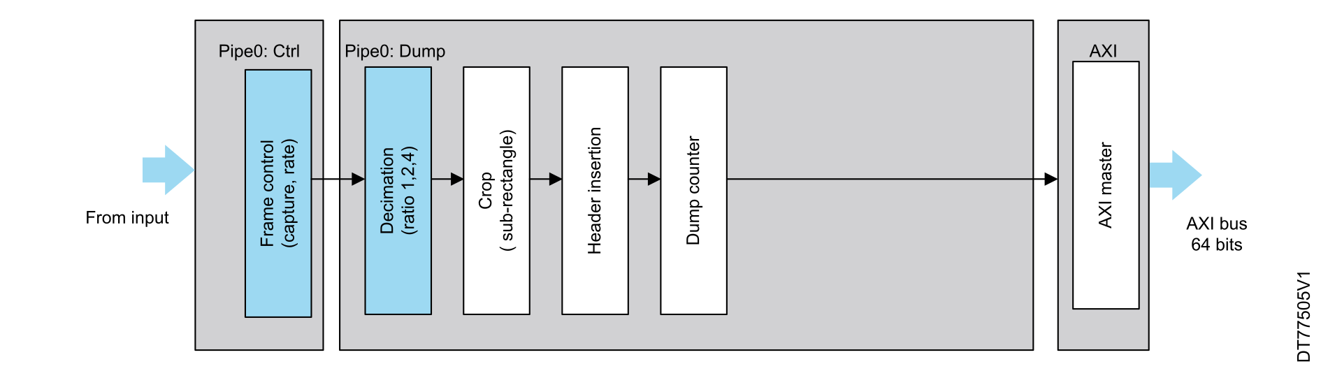
Figure 37. Capturing JPEG pixels using Pipe0

The user must ensure that the decimation and crop modules are disabled, as their functionalities are not supported when the pipe is processing JPEG format.

Note:

In byte stream mode, the bytes are dumped consecutively with only a 32-bit padding (if needed) at the end of the frame (or JPEG stream).

There is no 32-bit padding operation inside the stream until the VSYNC deassertion (end of frame, or end of JPEG stream).
DCMIPP use cases

The DCMIPP and other STM32 peripherals can significantly enhance computer vision applications on the edge.

Here are some application examples:

Table 6. DCMIPP application examples
CategoryApplication
Building
  • People counting
  • Occupancy estimation
Home
  • Home appliances
  • Home security
  • Door phone and home security
Retail
  • Customer behavior tracking
  • Shelf storage anomalies
City
  • Crowd behavior
  • Parking spot occupancy
AutomotiveDriver monitoring
Farming
  • Disease detection
  • Livestock health and position monitoring
Industrial
  • Defect detection
  • Visual anomaly detection
  • Industrial monitoring systems and automated inspection
Security and surveillance
  • Security and video surveillance
  • System control
  • Access control systems
Video streaming
  • Real-time video streaming
  • Battery-powered video camera

Parallel interface camera sensor module

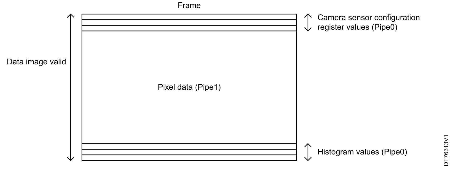
A parallel interface camera sensor can transfer images and statistics. It is easier to manage the software processing by splitting the statistics and the image data on different memory storages. Two pipes are used in such cases, with Pipe0 extracting the statistics and Pipe1 dealing with the image data (whatever the data format supported by the DCMIPP).

Both Pipe0 and Pipe1 work in parallel on the same frame, frame by frame.

Each output FIFO attached to the pipe conveys the data on the targeted memory for further processing. The camera sensor module may use some lines of the frame to transfer statistics or sensor configuration data. These lines can be placed at the beginning and at the end of the frame (see Figure 38 Use case: Pipe0 (statistics), Pipe1 (pixels)), even if there is no real standard.
Figure 38. Use case: Pipe0 (statistics), Pipe1 (pixels)

CSI-2 camera sensor module

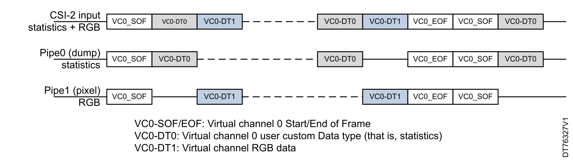
The CSI-2 protocol uses data types to distinguish between different data categories within a single virtual channel, involving two pipes (that is, Pipe0, and Pipe1). In Figure 39 Use case with CSI-2 interface: Pipe0 (statistics) and Pipe1 (pixels), the CSI provides two parallel data flows: RGB (or raw Bayer) and its sideband statistics.

The statistics are handled by the dump pipe (Pipe0), while the RGB data is sent to the pixel pipe (Pipe1).

The data flow starts with a virtual channel 0 start of frame (VCO_SOF), followed by data for statistics (VCO_DT0) and RGB data (VCO_DT1), and ends with a virtual channel 0 end of frame (VCO_EOF). The CSI-2 protocol distinguishes these data types using specific data type identifiers (DT) within the data stream, predefined codes representing different data types, and frame markers such as VCO_SOF and VCO_EOF.
Figure 39. Use case with CSI-2 interface: Pipe0 (statistics) and Pipe1 (pixels)

Example of ISP processing

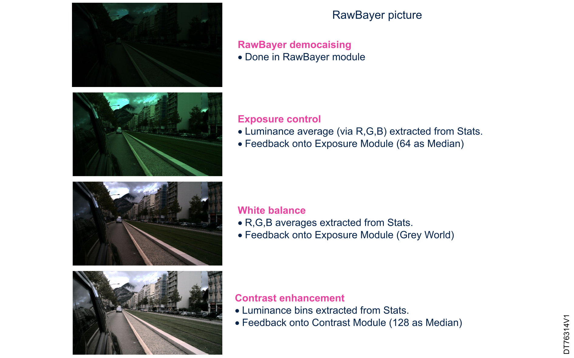
The ISP processing example illustrates the image-processing pipeline for a raw Bayer. The process begins with raw Bayer demosaicing, which is performed in the raw Bayer module to convert the raw image data into a full-color image. Then, Exposure Control is applied, where the luminance average (via R, G, B) is extracted from statistics. This information is fed back into the exposure module, using a median value of 64 to adjust the exposure settings.

Following this, White Balance is conducted by extracting the R, G, B averages from statistics and feeding this data back into the exposure module for each RGB component, after the Gray World algorithm (or similar) algorithm to ensure neutral color balance.

Finally, Contrast Enhancement is performed by extracting luminance bins from statistics and feeding this information into the contrast module, using a median value of 128 to enhance the contrast of the image. This step-by-step processing ensures that the final image is well-exposed, color-balanced, and has enhanced contrast for better visual quality.
Figure 40. Example of ISP processing
Hardware description

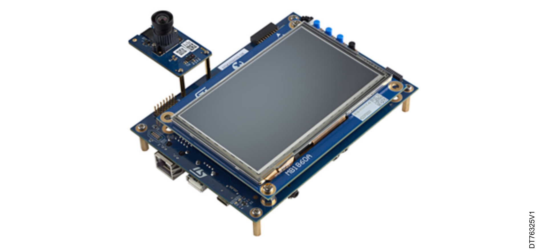
The hardware is composed of the MB1939 STM32N6570-DK development kit and the MB1854B IMX335 camera module (5Mpx/30fps), which is the default camera provided with the MB1939 board.

The STM32N6570-DK features the STM32N6570 microcontroller, designed for high-performance applications requiring advanced image processing and AI capabilities.

The MB1854B IMX335 camera module captures high-resolution images and video with its high-quality image sensor.
Figure 41. STM32N6570-DK development kit

The characteristics of the pins are as follows:

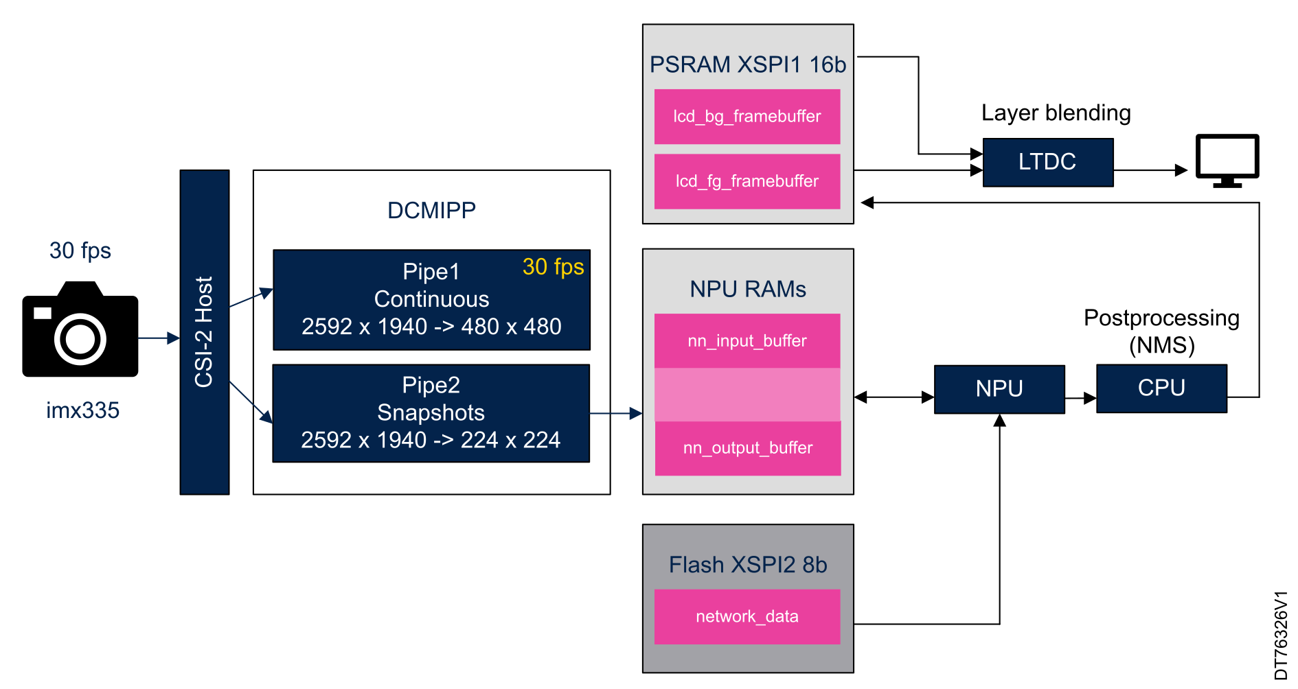
  • Pipe 1 is enabled to continuously transmit images from the imx335 sensor to the DISPLAY_BUFFER buffered.
  • Pipe 2 is enabled using to continuously transmit images from the imx335 sensor to the double-buffered.
The following table provides information about different framebuffers used in capture and inference in STM32N6x5/6x7.
Table 7. Framebuffer specifications and locations
Framebuffer nameSizeFormatLocation
LCD foreground buffer4608 KBRGB888 (800x480x3) x 4External XSPI1 PSRAM
LCD background buffer1500 KBARGB4444 (800x480x2) x 2External XSPI1 PSRAM
Input neural network buffer221 KBRGB88 (192x192x3) x 2External XSPI1 PSRAM
The DCMIPP interface features two pipelines: Pipe 1 for continuous image capture at a resolution of 2592 x 1940 downscaled to 480 x 480, and Pipe 2 for snapshots at the same resolution downscaled to 224 x 224.
Figure 42. DCMIPP use case example

STM32Cube examples

The STM32CubeH7RS and STM32CubeN6 MCU Packages offer a large set of examples implemented and tested on the corresponding boards.

The table below gives an overview of the DCMIPP examples and applications across various STM32Cube. All these examples are developed to capture RGB data. For most of the examples, the user can select one of the following resolutions: 800 x 480, 2592 x 1944.

Table 8. STM32Cube DCMIPP examples
MCU Package Project nameBoard
STM32CubeH7RSDCMIPP_ContinuousDBMSTM32H7S78-DK
DCMIPP_ContinuousMode
DCMIPP_JPEGSnapshotMode
STM32CubeN6DCMIPP_ContinuousDBMSTM32N6570-DK