AN6211 · Application noteIntroduction to digital camera interface pixel pipeline for STM32 MCUs
Download .pdfOpen in the full document

DCMIPP pixel format support

DCMIPP pixel format support

This section describes the pixel formats used in the parallel interface, pixel pipes, and dump pipe.

The DCMIPP supports the following data formats:

  • Monochrome (8, 10, 12, 14 bit)
  • RGB444, RGB565, RGB666, RGB888
  • Raw Bayer (8, 10, 12, 14 bit)
  • YUV422 and YUV444
Note:

The parallel interface does not input specifically RGB444, RGB555 and RGB666. However, a sensor with this output can connect them onto the DCMIPP, by selecting RGB565 and RGB888. The missing bits can then be connected or strapped to the MSB of the sensor output.

Wide input pixel formats can be sampled in single, double, triple, or quadruple cycles. The table below describes the input pixel formats for the parallel interface and the number of cycles of each format.

Table 4. Supported pixel formats on the parallel interface
I/O pin1 cycle2 cycles3 cycles4 cycles
Byte​X​-​-​-​
Raw 8-bit​X​-​-​-​
Raw 10-bit​X​-​-​-​
Raw 12-bit​X​-​-​-​
Raw 14-bit​X​-​-​-​
Monochrome 8-bit​X​-​-​-​
Monochrome 10​-bitX​-​-​-​
Monochrome 12-bit​X​-​-​-​
Monochrome 14​-bitX​-​-​-​
Sensor RGB444 to DCMIPP RGB565​X​-​-​-​
Sensor RGB555 to DCMIPP RGB565​X​-​-​-​
RGB565 – 8-bit​-​X​-​-​
RGB565 – 16-bitX​- - -​
RGB444 – 12-bit-​X​-​-​
Sensor RGB555 to DCMIPP-RGB565X​-​-​-​
Sensor RGB444 to DCMIPP-RGB565X​-​-​-​
RGB888 - 24-bit-​-​X​-​
YUV444 - 24-bit-​-​X​-​
Sensor RGB666 to RGB888-​-​X​-​
YUV422 - 16-bit (YUYV)-​X​-​-​

Monochrome pixel format

The DCMIPP supports monochrome formats with bit depths of 8, 10, 12, and 14 bits per pixel (bpp), which are used to represent different shades of gray. For example, an 8-bit monochrome image can display 256 shades of gray.

Raw Bayer pixel formats

The DCMIPP supports raw Bayer formats with bit depths of 8, 10, 12, and 14 bits per pixel (bpp). The raw Bayer format captures raw image data directly from the camera sensor without any color processing. The sensor pixels are arranged in a Bayer pattern, consisting of alternating rows of red, green, and blue filters.

Each pixel in the raw Bayer format represents only one color component (red, green, or blue), and the full-color image is reconstructed through a process called demosaicing.

The memory bits have the structure illustrated in Figure 17 DCMIPP data register filled with monochrome/raw Bayer data.

Figure 17. DCMIPP data register filled with monochrome/raw Bayer data

RGB pixel formats

RGB refers to red, green, and blue, which represent the three hues of light. Any color is obtained by mixing these three colors.

The different RGB formats (RGB444, RGB565, RGB666, RGB888) indicate the number of bits allocated to each color channel.

As an example, RGB888 is used to indicate that each pixel consists of 24 bits, divided as follows:
  • 8 bits for encoding the red value (the most significant 5 bits)
  • 8 bits for encoding the green value
  • 8 bits for encoding the blue value (the less significant 5 bits)
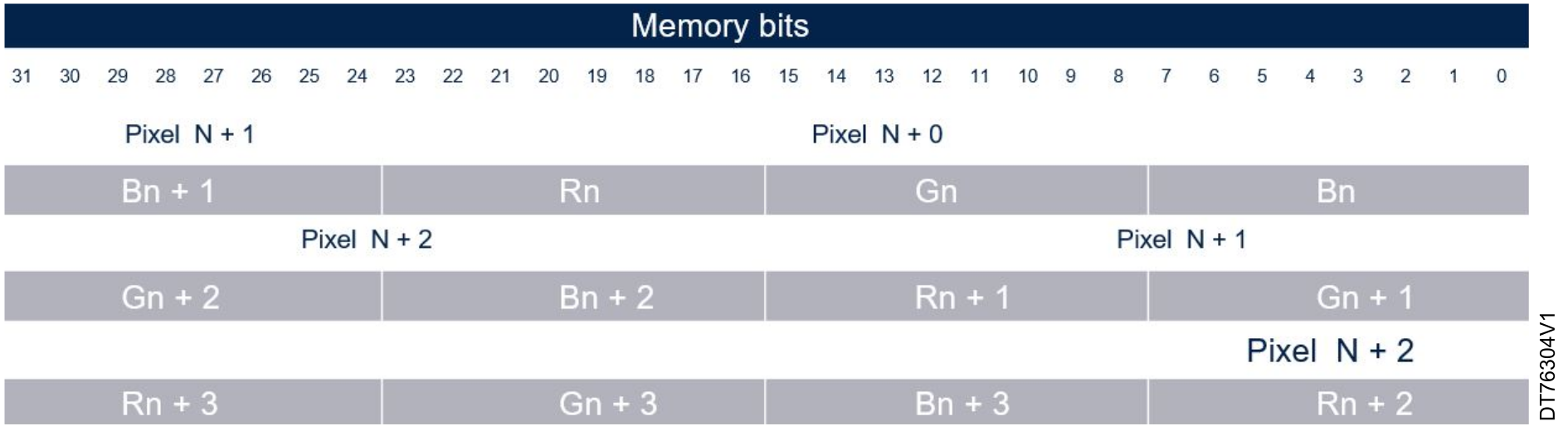
Each component has the same spatial resolution. Each sample has a red (R), a green (G) and a blue (B) component. Figure 18 DCMIPP data register filled with RGB data illustrate the memory bits containing RGB data, when an 8-bit data width is selected.
Figure 18. DCMIPP data register filled with RGB data

YUV pixel formats

YUV is a family of color spaces that separates the luminance or luma (brightness) from the chrominance or chroma (color differences).

YUV consists of three components:

  • Y refers to the luminance or luma (black and white)
  • U refers to the blue chroma
  • V refers to the red chroma

For YUV422-1 buffer (YUYV), each pixel is stored with 8 bits for Y (luminance), and the chrominance components U and V are shared between two pixels. Specifically, the memory layout alternates between Y, U, Y, V for consecutive pixels (that is, pixel N has Y0, U0, Y1, V0, and pixel N+1 has Y2, U1, Y3, V1).

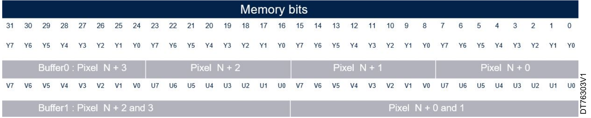
For example, in the YUV422-2 buffers configuration, the Y components are stored in one buffer and the U and V components are stored in another buffer. For instance, the buffer contains Y values for pixel N, N+1, N+2, and N+3, while buffer contains the U and V values for pixel N and N+1.

Figure 19 DCMI data register filled with YUV data illustrates the memory bits containing YUV422-1 data when an 8-bit data width is selected.
Figure 19. DCMI data register filled with YUV data