AN6211 · Application noteIntroduction to digital camera interface pixel pipeline for STM32 MCUs
Download .pdfOpen in the full document

AXI IP-Plug

AXI IP-Plug

The AXI IP-Plug is designed to manage data transfer from various pipes to memory using the AXI protocol. This module, shared by all pipes ensures efficient handling of data dumps from these pipes to memory.

The AXI IP-Plug is equipped with key features designed to optimize data transfer and memory management.

It includes Pipe ID differentiation to identify data sources and manage quality of service (QoS) accordingly. The FIFO buffers are sized to handle up to 2 microseconds of latency. It supports burst lengths of 64 and 128 bytes. The IP-Plug can manage up to 16 outstanding transactions simultaneously, addressing high-bandwidth requirements effectively. A bandwidth limiter is included to prevent memory overload by controlling the bandwidth usage of each pipe. Additionally, the unique AXI-QOS mechanism ensures that all pipes meet their real-time constraints without differentiation.
IP-Plug configuration steps

The following steps outline the programming procedure for accessing idle registers.

  1. Lock request

    The CPU requests to lock the IP-Plug by writing 1 in the P_START register flag.

  2. Status polling

    The CPU waits that the IDLE register flag is set to 1 by the IP-Plug.

  3. Programming
    The CPU writes all the required IP-Plug registers. This includes:
    • Setting the MEMORYPAGE register for efficient DRAM handling.
    • Identifying clients corresponding to each pipe or buffer.
    • Configuring OTR (outstanding transactions) for each client.
    • Setting FIFO size by configuring DPREGSTART and DPREGEND for each client based on their peak bandwidth requirements.
    • Setting TRAFFIC (burst size) for each client.
    • Allocating WLRU (bandwidth proportion) for each client.
    • Setting SVC (system virtual channel) for each client.
  4. Unlock

The CPU unlocks the IP-Plug by writing 0 in the P_START register flag.


In the STM32N6x5/6x7, the DCMIPP includes three pipes (Pipe0, Pipe1, Pipe2), with Pipe1 supporting full planar capability through three buffers (Y, U, V).

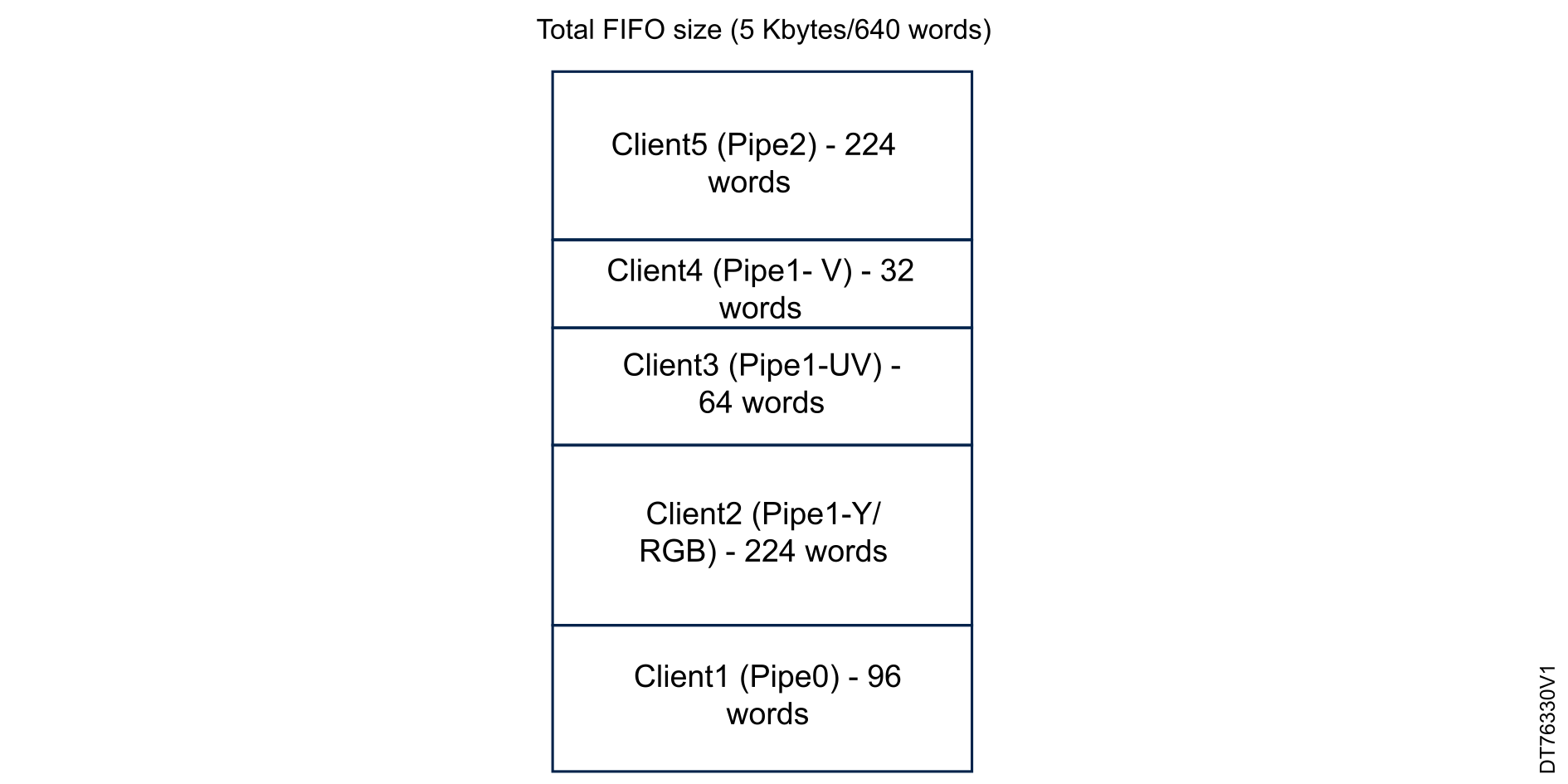
Each client of the IP-Plug is allocated a proportion of the total FIFO size and the total outstanding available transactions based on their bandwidth requirements. The total FIFO size is 5 Kbytes (5120 bytes), which translates to 640 words (since AXI width is 64 bits). The allocation of the FIFO size among the clients is illustrated in the diagram below. The parameters used for allocation are DPREGSTART, which is the starting word of the FIFO for the client (for example, Client1 starts at word 0), and DPREGEND, which is the ending word of the FIFO for the client (that is, Client1 ends at word 95). The total number of words for each client is calculated based on their allocated proportion of the total FIFO size.

The capabilities of the DCMIPP are shared among the clients The total bandwidth proportion, when all pipes are used, is 12 with the following assumptions:
  • Client1 for Pipe0: dump of raw Bayer pixels, padded to 16 bpp, BW = 2 / 12
  • Client2 for Pipe1-Y: dump of ARGB pixels, on 32 bpp, BW = 4 / 12
  • Client3 for Pipe1-UV: dump of UV components, on 8 bpp, BW = 1 / 12
  • Client4 for Pipe1-V: dump of V component, on 4 bpp, BW = 1 / 12
  • Client5 for Pipe2: dump of ARGB pixels, on 32 bpp, BW = 4 / 12
Figure 20. FIFO allocation among IP-Plug clients for STM32N6x5/6x7
Note: If a client is assigned 1 KB of FIFO space, which corresponds to 128 words, and DPREGSTART is 0, then DPREGEND would be 127. This is calculated as follows:

FIFO size in words = 1 KB / 8 bytes per word = 128 words

DPREGEND = DPREGSTART + (FIFO size in words - 1)

Overview

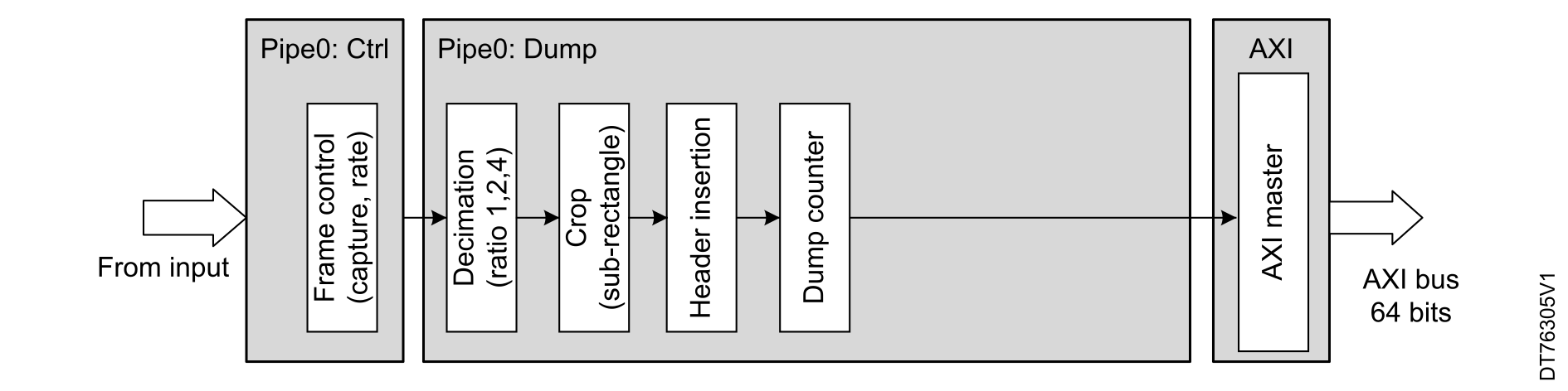
Pipe0 acts as a dump pipe, extracting data from the camera sensor module and transferring it directly to the targeted memory with basic decimation and 2D cropping operations. It retrieves data via the 16-bit parallel interface or the CSI-2 interface, managed by the INSEL bit in the DCMIPP_CMCR register. The flow selection determines the virtual channels and data types to be processed, while the frame controller handles the camera acquisition mode.

When valid input data is detected, 2D cropping and decimation can be configured by software. Dump counter and data limit ensure proper handling of data length within a frame. Pipe0 can be reconfigured periodically, with events triggering software reconfiguration routines. Shadow registers can be written during frame processing, with values loaded into physical registers at the start of the frame event.
Figure 21. Data flow and processing modules in Pipe0

Decimation

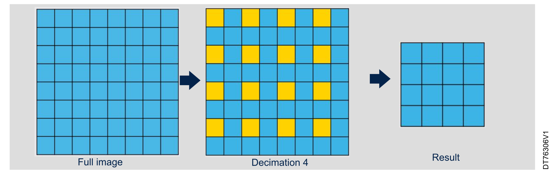
Decimation is used to reduce image resolution while maintaining the field of view. A typical application involves using a lower resolution image for live view to reduce camera bandwidth and increase the frame rate. This also helps in providing smaller images for neural network processing. It is possible to downsize a frame by a factor 2x, 4x and 8x in both horizontal and vertical directions.

The figure below illustrates an example of an image with a resolution of 4096 x 2048. In 4 x 4 decimation mode, the output resolution is 1024 x 512.
Figure 22. Decimation module

Pixel 2D cropping

The crop operation extracts and forwards a rectangle of pixels. The dump pipe (Pipe0) can handle 2D crop processing. Vertical cropping is based on lines, facilitated by the HSYNC event.

However, the horizontal cropping is applied based on 32-bit wide data rather than individual pixels, as this pipe does not directly consider pixels. Instead, it manages the data flow with 32-bit granularity.

Downsize

The downsize module implements a downsize based on box filtering, which allows ratios from 1x to 8x independently, in both X and Y directions.

Header insertion

The header insertion module is designed works with dump pipes and can insert a header before the data of a former CSI packet. This header can either be a frame sync short packet or a header of a long data packet. It helps software interpret the following data payload:
  • The frame sync short packet provides information about the frame type (SOF or EOF), frame number, and virtual channel ID.
  • The header of the data long packet provides information about the number of bytes in the payload, data type ID, and virtual channel ID.

Dump counter

The DCMIPP offers the capability to count the number of 8-bit data dumped within a frame for input data format with unknown length (JPEG for instance). It avoids dumping greater number of data which would compromise memory integrity if the reserved area for the dump is smaller than the number of data under capture.

The limit is set by the software in the DCMIPP_P0DCLMTR register. When this limit is reached, an interrupt may be generated to notify the software that any data beyond the limit is rejected, resulting in an incomplete frame acquisition. The counter continues to increment after the limit is crossed to indicate the amount of data that has been discarded, and it saturates at 0x03FF_FFFF.

Double buffer mode

The dump pipe uses an AXI master interface to dump the data from the internal FIFO to the external memory. In the application, it is possible to handle frame data swapping memory area frame by frame as illustrated in Figure 23 Double buffer example. The double buffer mode supports this function.

There are two memory address registers set to initialize the base addresses of these memories areas. Each start of captured frame event swaps the memory base address to handle double buffering mode.

Double buffer mode allosw postprocessing on a buffer (framebuffer) while the other buffer is read for display (display buffer) or used as input in the NPU.
Figure 23. Double buffer example

Pipe1: Main pipe, ISP part

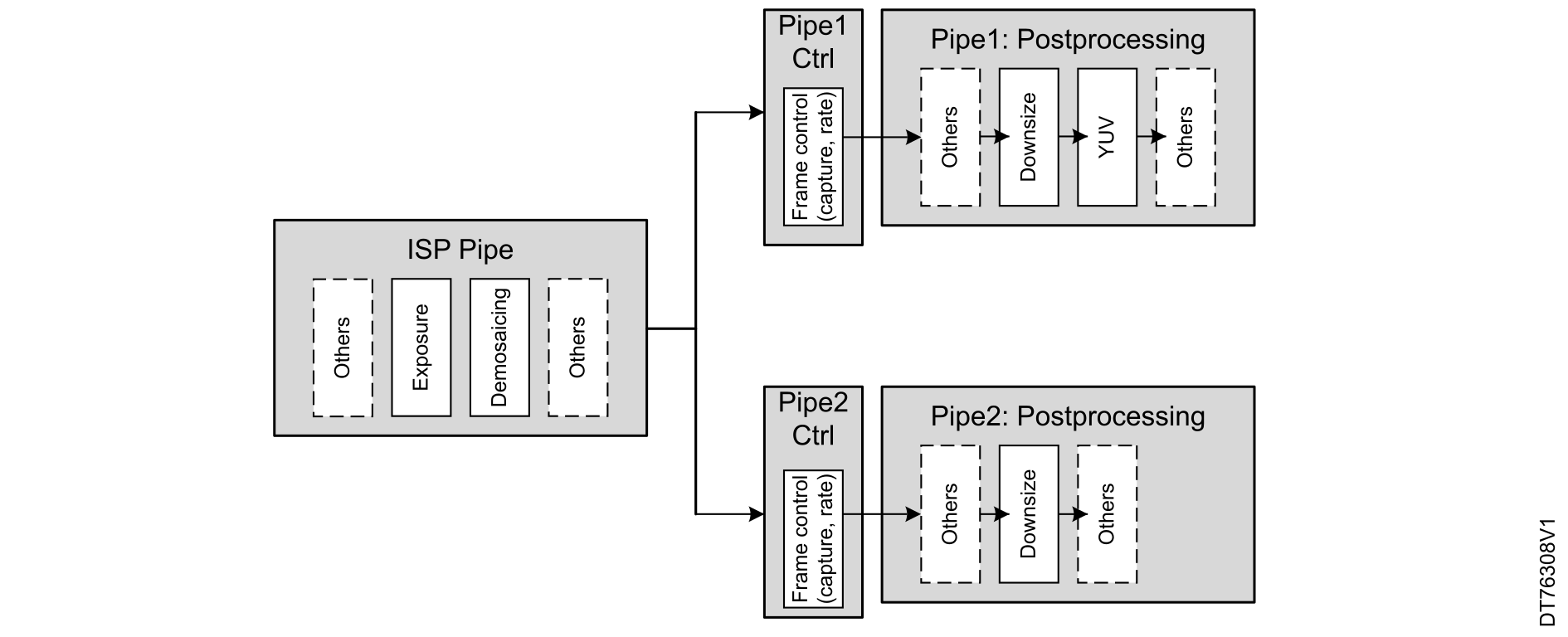
Pipe1 is a pixel pipeline that integrates various image signal processing (ISP) and postprocessing functions to relieve the software from specific time and memory-consuming operations. Pipe1 is typically used for primary tasks such as video encoding, software analysis, and neural networks. It allows for input downsizing, color conversion, and dumping to multiple pixel formats, including multi-planar ones.

Pipe1 can adjust luminosity through gamma conversion, perform autoexposure, and calibrate black levels using the embedded image-processing functions. This capability is particularly useful for handling camera sensors without internal ISPs. Additionally, Pipe1 can convert raw Bayer data to RGB (demosaicing). Importantly, Pipe1 shares all its image-processing functions with Pipe2.
Figure 24. Data flow and processing modules in ISP, Pipe1, and Pipe2

Pipe1 (ISP part)

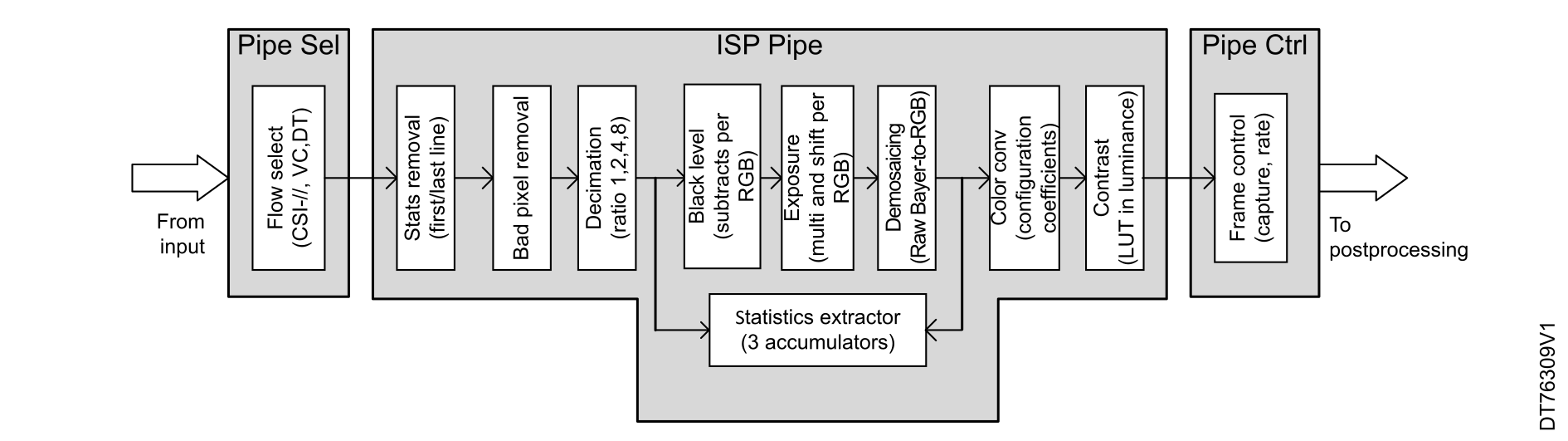
This section details each module in the ISP part, which implements various functions as illustrated in Figure 25 Data flow and processing modules in ISP Pipe. These functions include: statistics removal within the data flow, bad pixel detection to automatically remove noisy pixels, and basic decimation to reduce high-resolution camera sensor data to fit within the image-processing maximum resolution tolerance. Additionally, the ISP performs auto exposure and statistics extraction based on pixel analysis. It employs a demosaicing algorithm to convert raw Bayer input pixels to RGB, and includes color conversion and contrast enhancement functions.
Figure 25. Data flow and processing modules in ISP Pipe
Byte to pixel conversion

The module operates on pixel pipes by receiving 32-bit words from the input interfaces (parallel or CSI). It extracts pixels based on the provided pixel format and maps them into the triple-component pixel pipeline, which is 14 bits per component (bpc) at this stage and 8 bpc later downstream.

Note:

YUV420 to YUV444 conversion is not supported. Pipe1 and Pipe2 cannot extract and process YUV420 pixels received from the CSI interface.

Statistics removal

The module is used to remove potential statistic data inserted by a sensor, prior to starting the demosaicing conversion that is multipixel and would be impacted by remaining statistics. It is typically used by sensors with a parallel interface that cannot distinguish between statistics and pixel data. CSI-2 sensors typically split these flows using different virtual channel IDs.

Features:
  • Suppression of some of the first lines of the frame
  • Suppression of the last lines of the frame, after a configured line N
Bad pixel removal

This module aims at detecting and correcting artifacts generated by a bad pixel on the sensor array. It is based on a correlation extraction, and not on fixed locations.

Input decimation

The decimation is redundant with the downsize, that brings a higher quality (the decimation discards the data of the dropped pixels, while the downsize averages all pixels and does not lose information).

The decimation has two main usages:

  1. Reduces the width of very high-resolution sensors to one accepted by the raw Bayer to RGB conversion. Indeed, the raw Bayer to RGB embeds a line buffer that limits the processed images to a maximum width of 2688 pixels. For instance, to plug a 12 megapixel sensor (4000 x 3000), decimate its width by a factor 2x to 2000 pixels wide, and have it converted to RGB.
  2. Complements the downsize (limited to ratio of 8 x 8), to have a combined downsizing ratio of 64 x 64. It is recommended to have the largest ratio implemented in the downsize, and the decimation complement to that. For instance, for a ratio 30x, it is recommended to have a ratio 4x in decimation, and a ratio 30 / 4 = 7.5 in the downsize.
Statistics extraction

This module extracts frame statistics to provide inputs for software image compensation algorithms. These algorithms then adjust hardware modules such as black level calibration, exposure compensation, white balance, and contrast enhancement based on the feedback.

Statistics are accumulated during a full frame and sampled at the end, allowing the software the entire next frame to read the accumulated data.

The module features three accumulators, enabling the extraction of three pieces of information per frame. It can focus on specific subscenes by extracting statistics from a designated subrectangle and can select specific components, such as R, G, B, or luminance.

Two types of statistics can be extracted: the average and the spectrum, which is split into 12 bins across the range of 0 to 255.

Note:

One limitation is that constructing a 12-bin spectrum with three data points per frame requires four frames, which reduces reactivity

Black level calibration

This module suppresses a potential positive black level offset, which happens when the sensor sends non-null pixels when capturing a black picture.

Exposure and white balance

This module aims to compensate for bad exposure, whether too short and dark or too long and light, and corrects color balance to achieve a more neutral white.

The exposure and white balance operations are purely linear, ensuring no color distortion if performed correctly.

The module reduces the pixel dynamic range from 14 bits to 8 bits, lowering the implementation cost of downstream modules, which operate at 8 bits instead of 14.

It also recenters the RGB values towards a neutral white color scene. The module features linear amplification applied to the input component, which is then saturated to 8 bits, minimizing color distortions among R, G, and B.

It selects an 8-bit dynamic range from the 14-bit input: the eight most significant bits (MSB) for well-lit scenes, the eight least significant bits (LSB) for dark scenes, or any intermediate range for medium lighting.

The amplification is configurable via software to adapt to the scene, utilizing statistical extractions to compute the ideal amplification coefficient. Additionally, it differentiates between R, G, and B to recenter the colors to white.

Demosaicing

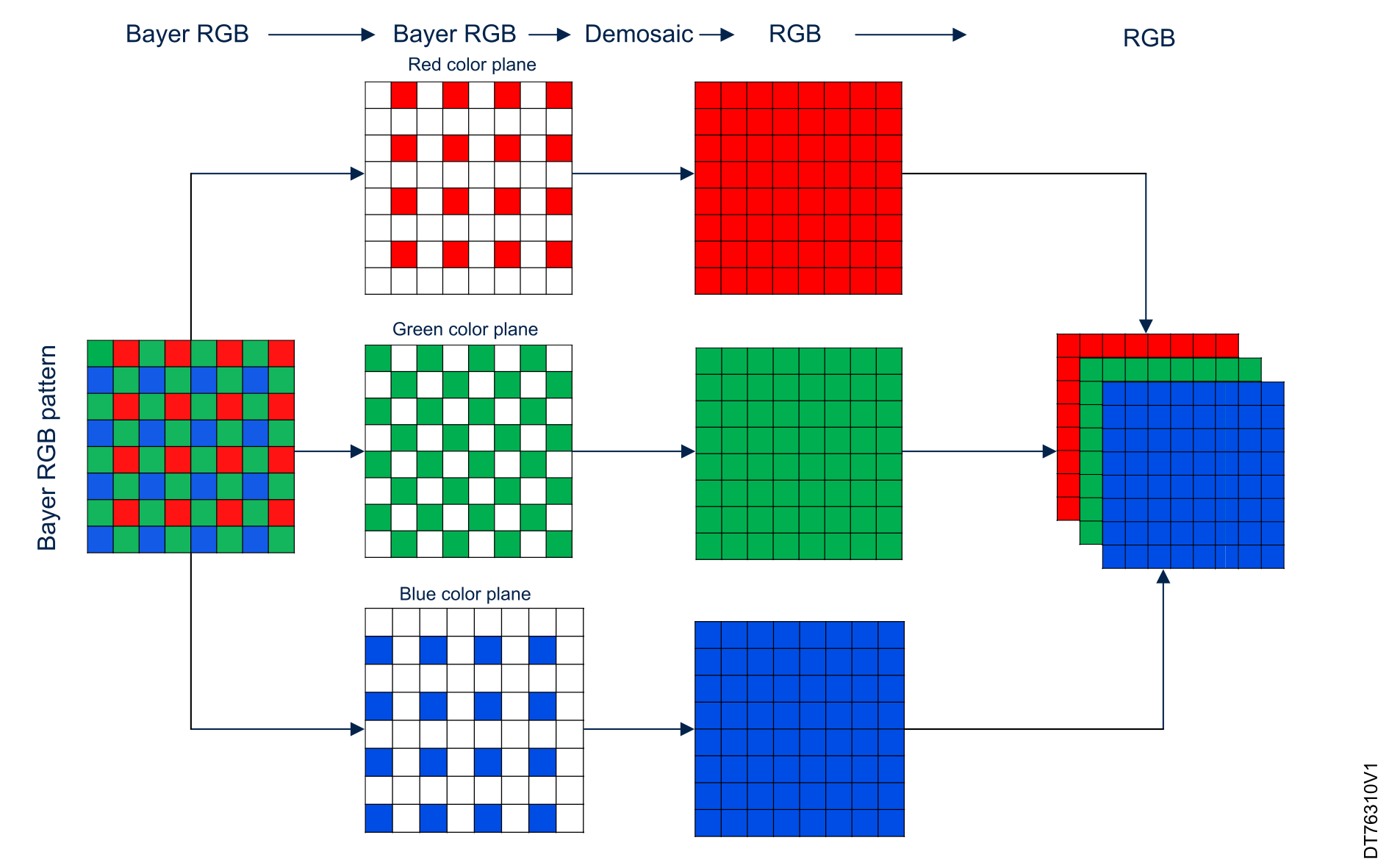
The module works on the pixel pipes and implements a mid-quality conversion from raw Bayer 8 bpp to an RGB 24 bpp, with no implicit half-sizing: the output RGB pixel rate is the same as the input component rate.

The conversion targets real-time but medium quality purposes, such as display or low-resolution software analysis. For higher-quality conversions, it is recommended to convert the raw Bayer in software, with higher-quality algorithms but limited to non-real-time, thus still-picture applications. The algorithm takes the surrounding 3 x 3 components in input, applies linear heuristics to determine the most likely missing components, and generates an output RGB888 pixel as illustrated in Figure 26 Demosaicing module.

To provide the 3 x 3 input matrix to the algorithm, the demosaicing module embeds a double line-buffer, 2 x 2688 components wide. As such, it limits the maximum width of a converted demosaicing buffer to 2688 components per pixels wide. Wider camera sensor resolution can be connected and goes through the first decimation stage in front of the demosaicing operation.
Figure 26. Demosaicing module
Note:

This demosaicing conversion algorithm can create some artifacts such as zipper. These artifacts are reduced by a later downsizing or even suppressed with a 2 x 2 downsizing.

Contrast enhancement

This module concludes the image-processing pipeline by enhancing the frame contrast through nonlinear emphasis of pixel luminance. It increases the number of luminance quantification steps in frequently used luminance ranges (typically central grays) while reducing steps in less used ranges (usually very dark and very light pixels). The purpose of this approach is to address parts of the scene that may be too dark or too light.

The contrast module nonlinearly amplifies the luminance of RGB pixels to improve visibility. It extracts pixel luminance based on local R, G, and B values and applies an amplification factor dependent on the luminance, interpolated from a table with nine entries. This process amplifies or reduces per-pixel luminance and proportionally adjusts the R, G, and B values.

Color conversion

This module implements color conversion with flexible and fully programmable coefficients. The goal of this module is to perform color correction to compensate for ambient illumination (such as sunlight, incandescent, or fluorescent lighting) and sensor distortions. It also maps colors to a neutral RGB.

It also supports YUV sensors by converting YUV data to standard RGB.

The module features the multiplication of input R, G, B (or YUV) values by a 3 x 3 matrix and the addition of an offset. It is fully configurable via software and can be clamped to a reduced dynamic range if necessary.

Pipe1: Main pipe, postprocessing part

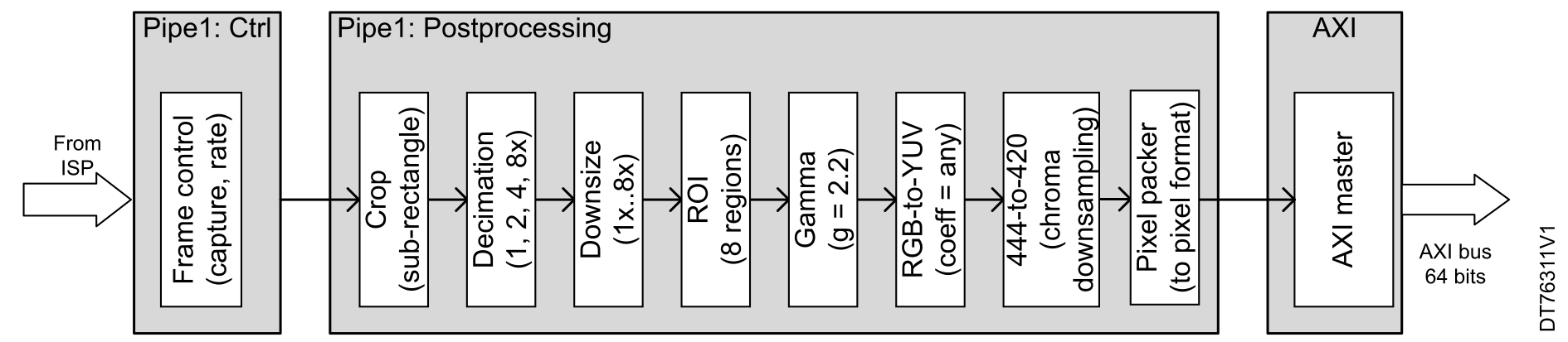
The postprocessing Pipe1 (illustrated in Figure 27 Data flow and processing modules in Pipe1) is a pixel pipeline in which postprocessing functions are integrated. The input is from ISP pipe. The applicative Pipe1 is the most featured pixel pipeline, even if the image‑processing functions can be shared with Pipe2.

Once the input source is chosen, the data enters Pipe1: Control, where the frame control module manages the capture rate. Then, the data proceeds to Pipe1 postprocessing, which includes several modules. After these processing steps, the data is passed to the pixel packer, which prepares it for transmission to the final output. The AXI master module then sends the processed data over a 64-bit AXI bus with a 2 μs latency.

Pipe1 integrates postprocessing modules to relieve the software from time and memory-consuming operations. These functions include cropping to retain only the necessary part of the image for the targeted application, decimation as a cost-effective preprocessing step before downsizing, and downsizing to reduce image resolution.

Additionally, it handles ROI signaling that helps object detection applications, gamma correction before sending data to memory for display operations, and YUV conversion with optional down-sampling to optimize memory usage or match a YUV420 video encoder.
Figure 27. Data flow and processing modules in Pipe1

Pixel 2D cropping

The pixel 2D cropping aims at extracting and forwarding a rectangle of pixels. The cropping assigns an X and Y location to the input pixels, selects a configured rectangle among the pixels, and forwards the pixels of this rectangle farther in the pixel pipe. The pixels around the selected rectangle are discarded.

Regions of interest (ROI)

Pixel pipes can define up to eight different ROIs to highlight areas in a picture. The purpose of this feature is to draw one rectangle with user size defined for each enabled ROI.

There is no hardware processing within the defined area applied on the image.

As the aim is to draw rectangles on a display, the ROI is supposed to be used when the data flow is RGB at the output of the image-processing blocks.

Gamma conversion

This feature implements a gamma compression on each R, G, B component, using a static gamma exponent 2.2. It stores gamma-compressed pictures, as defined in IEC 61966-2-1.

YUV conversion

This module converts the pixels to YUV for JPEG or video encoding applications.

Chroma-down sampling

The chroma-down sampling module reduces the chroma resolution from the YUV444 format (arriving) to the potential YUV420 output and sends them to a different channel.

Pixel packing

This module operates on the dump pipe (Pipe0) and pixel pipes (Pipe1 to N), organizing the incoming pixels into memory words.

It maps the RGB or YUV data pipeline to standard memory words, supporting various pixel formats.

For RGB:

  • ARGB8888
  • RGBA8888
  • RGB888p
  • RGB565

For YUV:

  • 8 bpp for monochrome
  • 1-buffer (444, 422)
  • 2-buffer (422, 420)
  • 3-buffer (420)

Additionally, it offers the capability to swap R and B (and Cr and Cb) components for more flexibility.