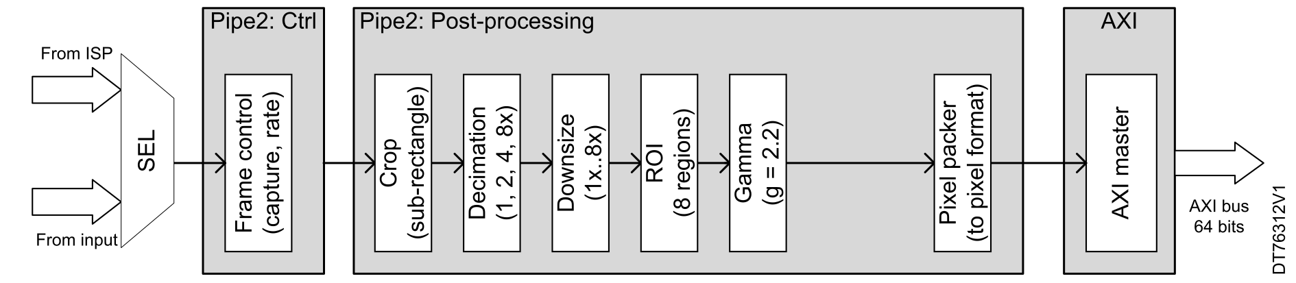
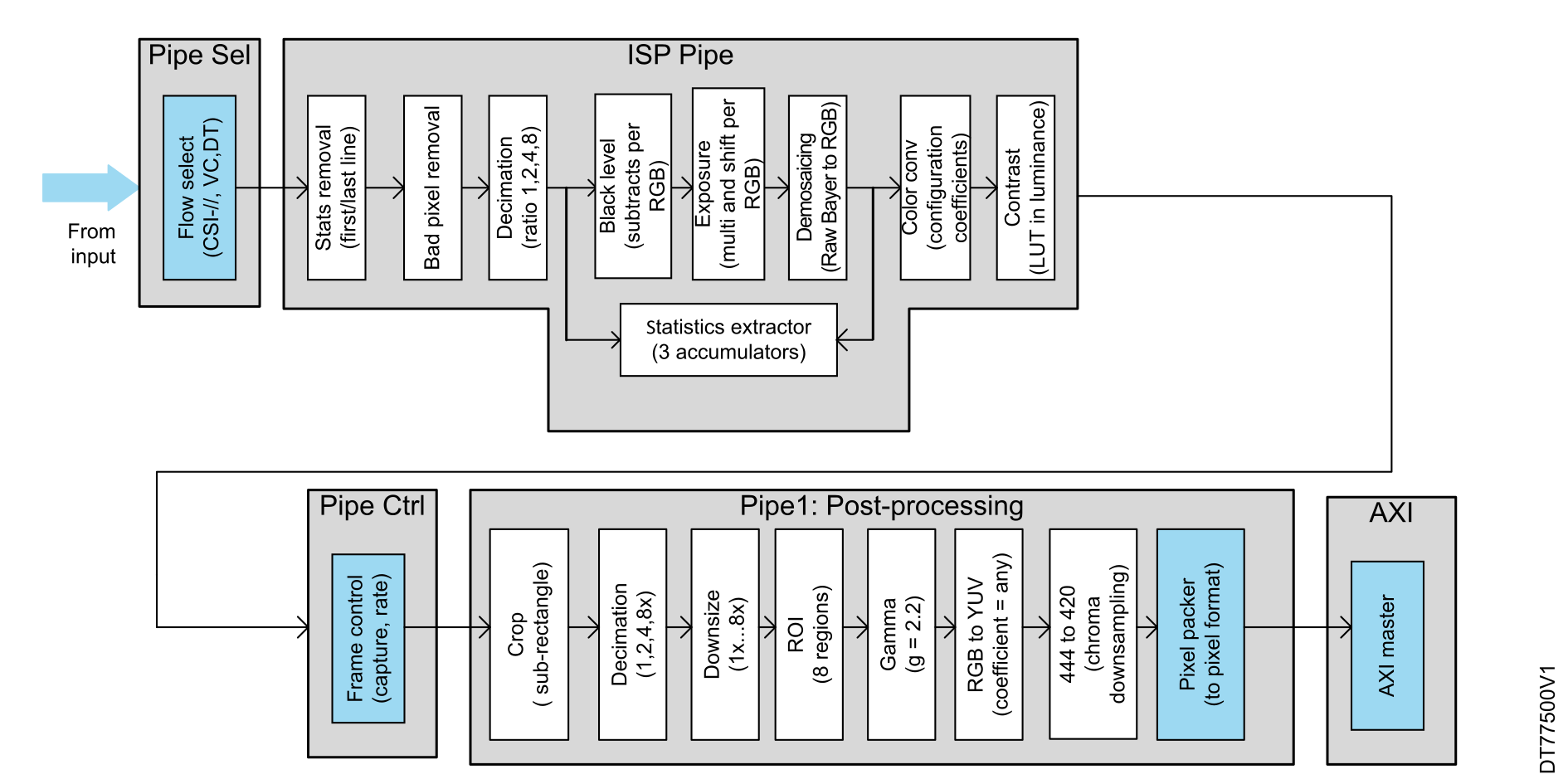
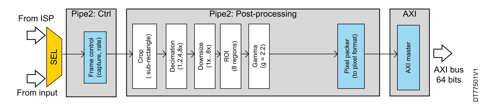
The main components of Pipe2, including the controller and general postprocessing functions, are almost identical to those of Pipe1. However, Pipe2 is a lighter pixel pipeline. It can operate in standalone mode or share image‑processing functions with Pipe1. As illustrated in Figure 28 Data flow and processing modules in Pipe2, this pipeline manages the input and output flow within the image-processing system. The input can be selected from either the ISP (image signal processor) or a direct input virtual channel through a selector (SEL). The AXI master module then sends the processed data over a 64-bit AXI bus.Figure 28. Data flow and processing modules in Pipe2
The set of postprocessing blocks is reduced compared to Pipe1, as neither the YUV conversion nor the down-sampling YUV444 to YUV420 are integrated in Pipe2. This pipe can have its own image crop area, dedicated downsizing, and it takes benefit of the gamma correction, similar to Pipe1.
ISP calibration and IQTune tool
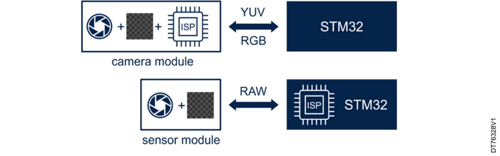
In contrast to a camera module that includes the lens, image sensor, and ISP, the raw sensor module only includes the lens and image sensor
The ISP processes the raw data from the sensor to produce a viewable image. It handles tasks such as white balance and color correction.Figure 29. Raw sensor module integration
The STM32 ISP IQTune tool
The STM32 ISP IQTune is a comprehensive STM32 ISP tuning software application offering a wide range of features and services to STM32 embedded ISP users.
It consists of two components:
A desktop application, running on a host computer (Linux®Ubuntu®, Windows® or macOS®).
An embedded application, running on the STM32 device to be tuned.
Linux® is a registered trademark of Linus Torvalds.
Ubuntu® is a registered trademark of Canonical Ltd.
Windows is a trademark of the Microsoft group of companies.
Ubuntu® is a registered trademark of Canonical Ltd.
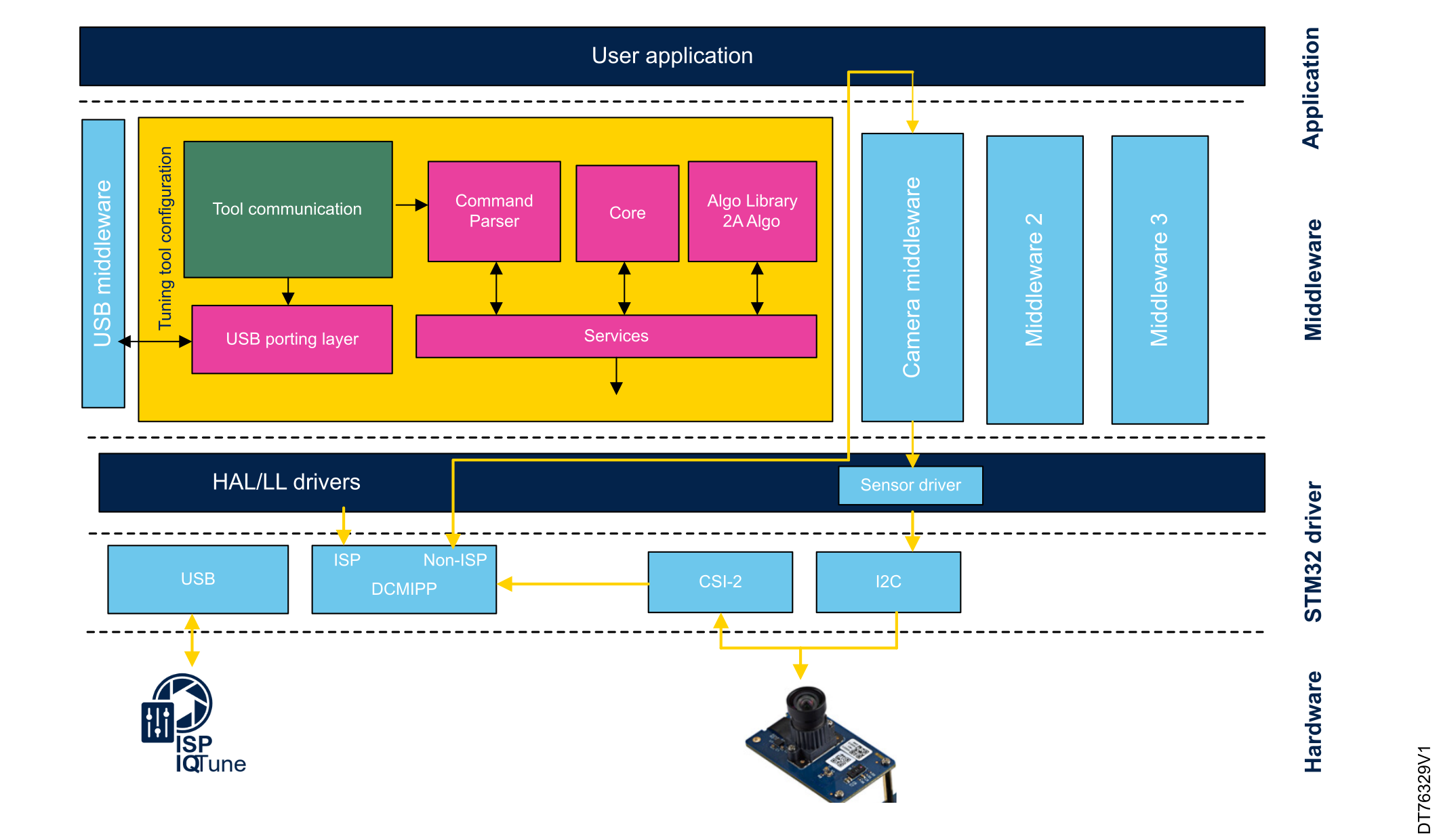
The embedded application architecture includes two middleware components to interface with USB and the IMX335 camera sensor. The user application, running on the target device, enables interaction between the STM32 ISP IQTune software (executed on the host) and the target device, allowing users to control and adjust ISP parameters.Figure 30. ISP IQTune application architecture
STM32 ISP IQTune provides all the services for users to tune the STM32 ISP for an RGB raw Bayer sensor and its associated lens. It provides image quality analyzing capabilities to easily tune the STM32 ISP for any lighting conditions.
For a white-balance profile, the image quality analyzing services provide:
The possibility to define the white-balance ISP gain.
The possibility to define the color correction matrix.
Information and metrics about the color accuracy according to the ISP configuration defined by the user.
ISP for a raw sensor
Illuminants, also called different light sources, have varying spectral distributions and color temperatures (measured in Kelvin) that can affect how the colors are captured by the camera sensor. The white balance adjustment (ISP gain) ensures that the whites are accurately represented, and the color adjustment (color correction matrix) ensures that the colors in the captured image closely match the actual scene.
ISP parameters for different lighting conditions must be tuned during the camera application development process. It ensures that the sensor and lens connected to the device can produce good image quality in terms of white balance and color accuracy under different lighting conditions, meeting user application needs. The results of the tuning procedure are a set of parameters programmed in the ISP and controlled by ISP algorithms.
Note: For more details about how to tune ISP using the STM32 ISP IQTune, users can check How to tune ISP using the STM32 ISP IQTunewiki article.
The ISP needs to be tuned when used with an RGB raw sensor. With a monochrome raw sensor, the ISP does not need to be tuned.
DCMIPP pipeline configuration for various sensor types
This section includes configurations for different types of sensors, including RGB, raw Bayer, monochrome (grayscale), YUV, and JPEG sensors. Each section provides specific instructions for setting up and capturing data from these sensors using the DCMIPP pipes of the STM32 microcontroller.
Configuration for RGB sensors
Incoming RGB pixels from the sensor can be captured by Pipe0, Pipe1, or Pipe2, depending on the DCMIPP capabilities of the STM32 microcontroller.
Pipe0 configuration
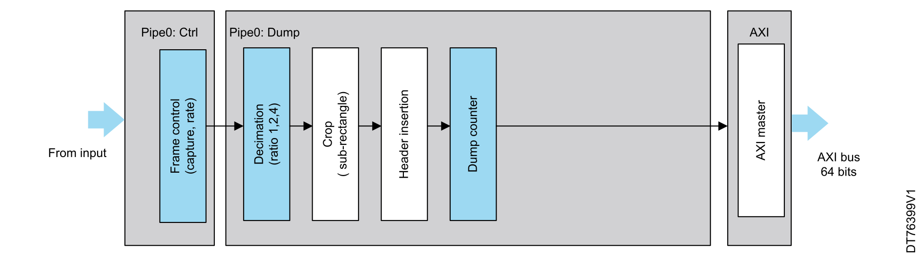
The dump pipe supports more formats than the pixel pipe. One of these formats is the RGB data type. Before Pipe0 retrieves data through the 16-bit parallel interface or the CSI-2 interface connected to the RGB sensor module, the flow selection module must be configured to handle the choice of virtual channels, data, and the acquisition interface.
To correctly capture RGB pixels and write them to the memory using Pipe0, the sensor should be set to output in the adequate RGB format, and Pipe0 needs to be configured to capture frames. Additionally, 2D-cropping and decimation operations can be configured by the software if needed. A dump counter is available to handle unknown lengths of data or to limit the amount of data within a frame. The pixel packer stage packs the pixels into the desired format and buffer, which serves as the storage area for the data.
Figure 31. Capturing RGB pixels using Pipe0
Pipe1 configuration
The same applies to Pipe1. The flow selection module and frame control are replicated for each dump and pixel pipe, managing the same parameters (CSI-//, VC, DT) along with the capture mode (continuous, snapshot) and rate settings of frame control. The pixel packer module then works on the dump pipe (Pipe0) and pixel pipe (Pipe1), setting the arriving pixels into memory words.
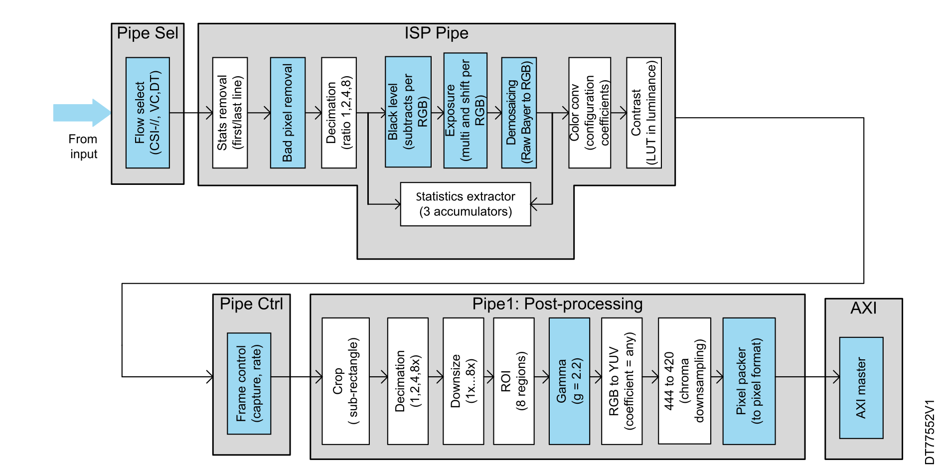
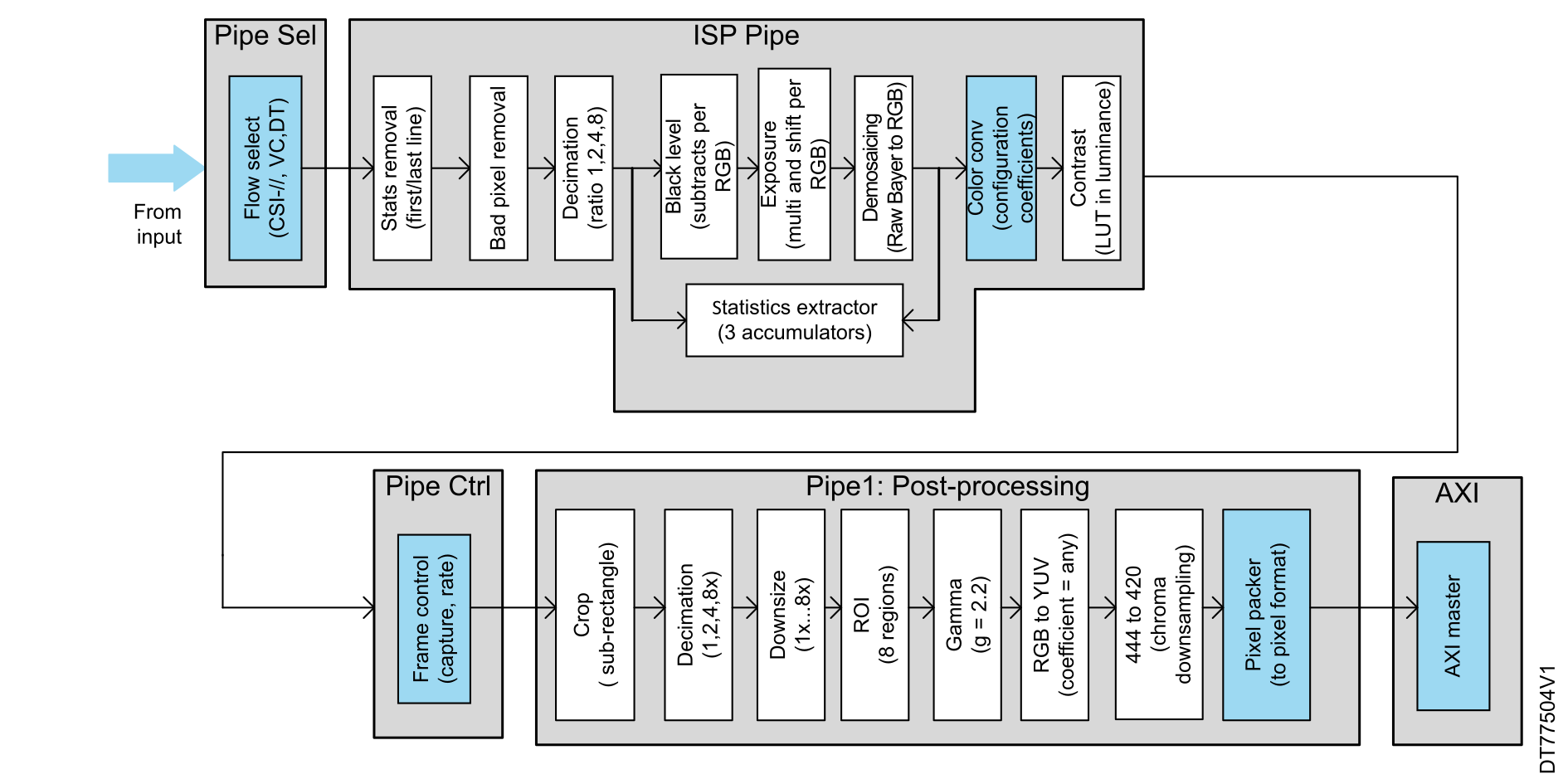
To capture RGB pixels and write them to memory using Pipe1 (which additionally handles image processing (ISP) and post-processing alongside pixel dumping), the modules highlighted in Figure 32 Capturing RGB pixels using Pipe1 should be enabled. The remaining modules, such as decimation and downsize, are optional and can be utilized for additional image-processing functions.Figure 32. Capturing RGB pixels using Pipe1
Pipe2 configuration
To capture RGB pixels and write them to memory using Pipe2, the user needs to configure the pixel packer registers with the following settings:
Specify the pixel format
Set the width of the image in pixels
Define the line stride (pitch) in bytes, which is the number of bytes between the start of one line and the start of the next line (that is, 5760 bytes for RGB888 format)
Set the height of the image in pixels
Figure 33. Capturing RGB pixels using Pipe2
Configuration for raw Bayer sensors
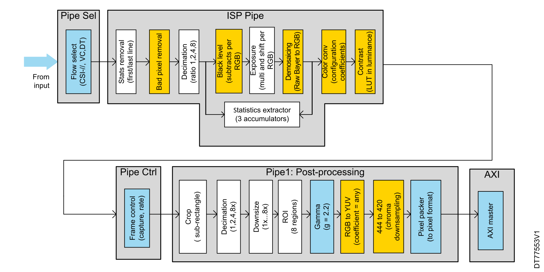
This section focuses on capturing raw Bayer pixels from the sensor and transferring the processed data to the memory. The raw Bayer pixels must pass through the highlighted modules in Figure 34 Capturing raw Bayer pixels using Pipe1 to be converted into RGB pixels:
Bad pixel removal: enable this module to detect and correct artifacts from the sensor.
Black Level: this module adjusts the black level offset, which occurs when the sensor sends non-null pixels while capturing a black picture. R, G, and B component offsets are subtracted from the R, Gr, Gb, and B Bayer components.
Exposure: this module multiplies the R, G, and B components by a configurable gain such as to recenter the colors to more accurate white tones.
Demosaicing: this module implements a mid-quality conversion from raw Bayer 8 bpp to RGB 24 bpp. The output RGB pixel rate matches the input component rate.
Gamma: this module applies gamma correction to each R, G, and B color component as defined in the sRGB standard.
Pixel packer: once data is converted, this stage packs the processed pixels into the desired format.
The remaining modules are optional and can be used for additional image-processing functions.
Figure 34. Capturing raw Bayer pixels using Pipe1
Configuration for monochrome (grayscale) sensors
To capture and process grayscale image data from a monochrome sensor, the user can utilize either the dump pipe or the pixel pipe (Pipe1) for further processing. For incoming grayscale pixels, it is necessary to enable the flow selection to direct the data flow through Pipe1. In this configuration, the following modules should be disabled: bad pixel removal, black level, demosaicing, color conversion and contrast.
Figure 35. Capturing monochrome pixels using Pipe1
Configuration for YUV sensors
To capture YUV pixels from YUV sensors and process them, either dump pipe (Pipe0) or pixel pipes (Pipe1, Pipe2) can be used. Dumping through Pipe0 is ideal for applications that require luminance and chrominance information. Alternatively, using Pipe1 to process YUV data and convert it to RGB using the ColorConv stage.
Pipe0 and Pipe1 configuration
In the YUV configuration with either Pipe0 or Pipe1, the same modules are activated as for RGB sensors, with the only difference being the change of data type in the module flow selection.
Pipe1 configuration
To process the YUV pixels and convert them to RGB format using the ColorConv module, enable the highlighted modules, namely flow select, Colorconv, frame control, and pixel packer, as they are essential. The rest of the post‑processing modules are optional such as the downsize stage for minimizing resolution or the chroma down-sampling module for reducing chroma resolution from the incoming YUV444 format to a potential YUV420 output.