DCMI description
This section details the DCMI, and its manner of dealing with the image data and the synchronization signals.
Note:
The DCMI supports only the slave input mode.
The DCMI supports only the slave input mode.
The DCMI comprises up to 17 inputs. Depending on the number of data lines enabled by the user (8, 10, 12, or 14), the number of the DCMI inputs varies (11, 13, 15, or 17 signals).
If less than 14-bit data width is used, the unused pins must not be assigned to the DCMI through GPIO alternate functions. The unused input pins can be assigned to other peripherals.
In the case of embedded synchronization, the DCMI needs only nine inputs (eight data lines and DCMI_PIXCLK) to operate properly. The eight unused pins can be used for GPIO or other functions.
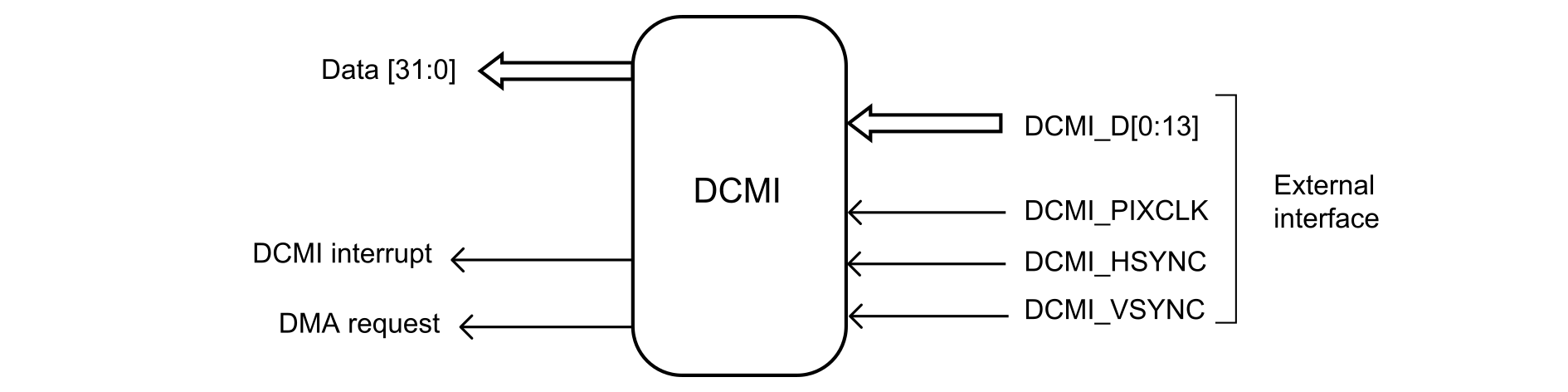
If x-bit data width is chosen (x data lines are enabled, x = 8, 10, 12, or 14), x bits of image (or video) data are transferred each DCMI_PIXCLK cycle, and packed into a 32-bit register.
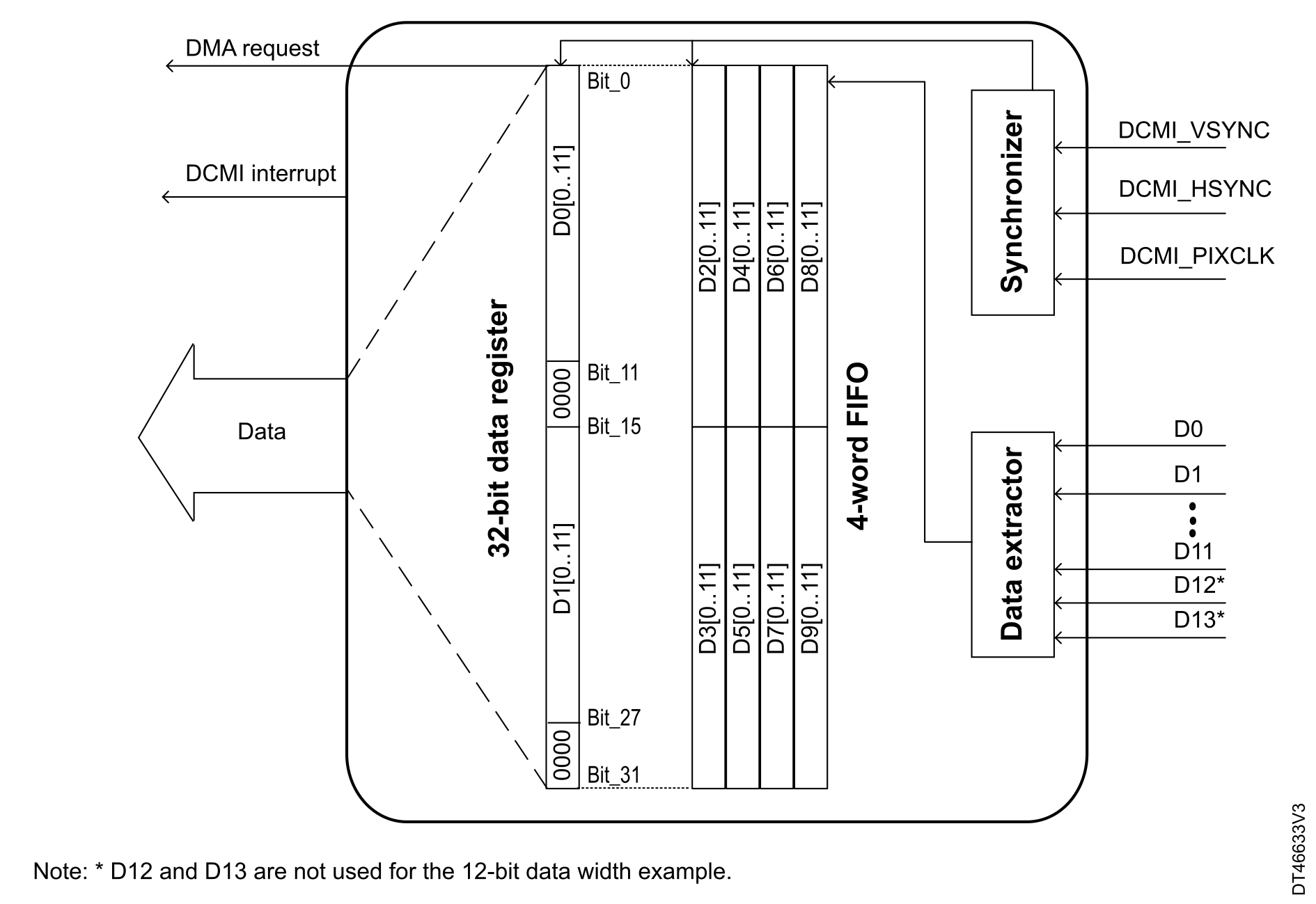




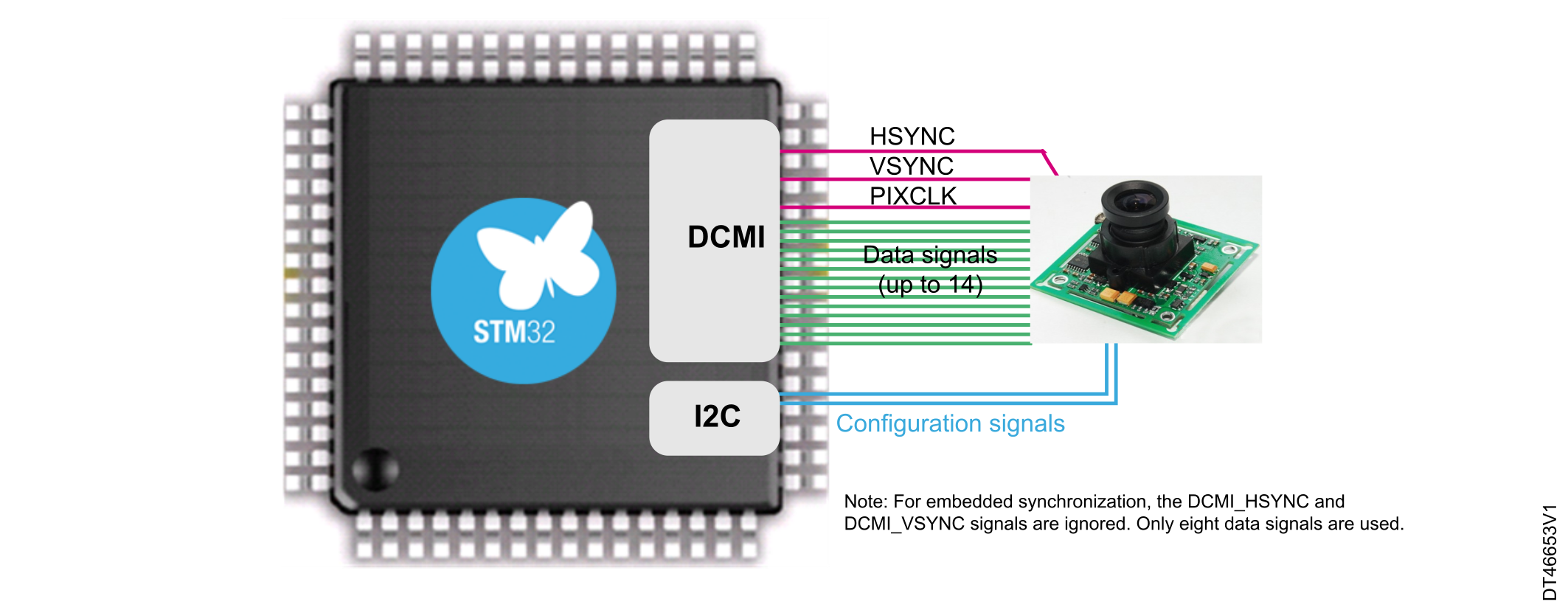
It is assumed that all image preprocessing is performed in the camera module.
The DCMI_PIXCLK and AHB clocks must respect the minimum ratio AHB/DCMI_PIXCLK of 2.5.
Some camera modules support the two types of synchronization, while others support either the hardware or the embedded synchronization.
The polarities of the DCMI_PIXCLK and the synchronization signals (DCMI_HSYNC and DCMI_VSYNC) are programmable.
Data are synchronized with DCMI_PIXCLK, and change on the rising or falling edge of the pixel clock, depending on the configured polarity.
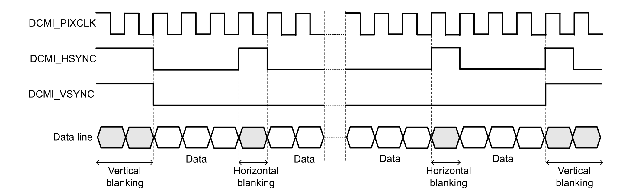
If the DCMI_VSYNC and DCMI_HSYNC signals are programmed active level (active high or active low), the data is not valid in the parallel interface when VSYNC or HSYNC is at that level (high or low).
The DCMI_HSYNC and DCMI_VSYNC signals act like blanking signals, since all data received during DCMI_HSYNC/DCMI_VSYNC active periods are ignored.
For compressed data (JPEG), the DCMI supports only the hardware synchronization. Each JPEG stream is divided into packets, which have programmable size. The packets dispatching depends on the image content, and results in a variable blanking duration between two packets.
DCMI_HSYNC is used to signal the start/end of a packet. DCMI_VSYNC is used to signal the start/end of the stream.
If the full data stream finishes and the detection of an end-of-stream does not occur (DCMI_VSYNC does not change), the DCMI pads out the end-of-frame by inserting zeros.
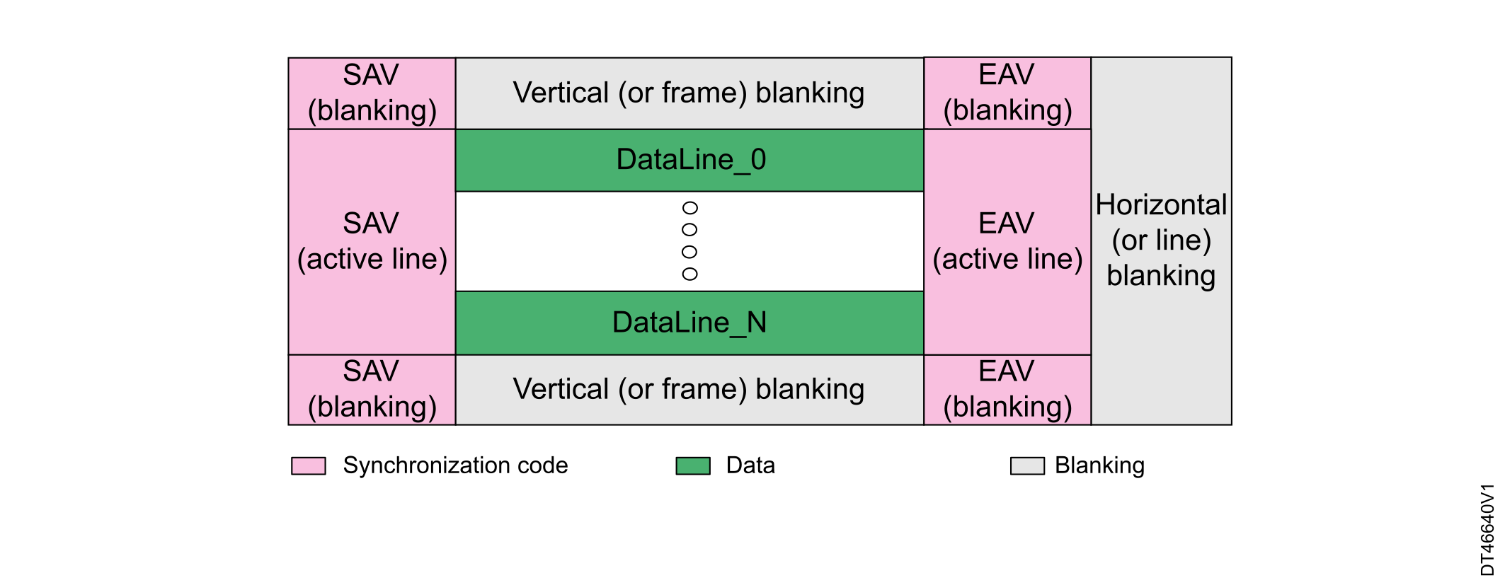
In this case, delimiter codes are used for synchronization. These codes are embedded within the data flow to indicate the start/end of line or the start/end of frame.
These codes are supported only for 8-bit parallel data interface width. For other data widths, this mode generates unpredictable results, and must not be used.
The codes eliminate the need for DCMI_HSYNC and DCMI_VSYNC to signal the end/start of the line or the frame. When this synchronization mode is used, there are two values that must not be used for data: 0 and 255 (0x00 and 0xFF). These two values are reserved for data identification purposes. It is up to the camera module to control the data values. Image data can then have only 254 possible values (0x00 < image data value < 0xFF).

This mode is ITU656 compatible (ITU656 is the digital video protocol ITU-R BT.656).
A 0xFF value programmed as a frame-end (FE) means that all the unused codes (the possible values of codes other than FS, LS, LE) are interpreted as valid FE codes.
In this mode, once the camera interface has been enabled, the frame capture starts after the first occurrence of an FE code followed by an FS code.
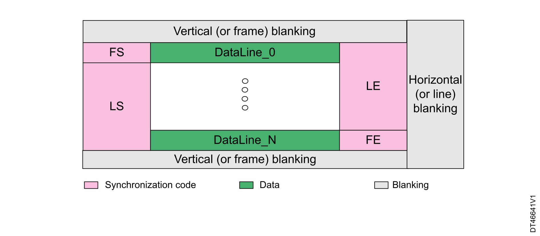
The camera modules can have up to eight synchronization codes in interleaved mode. This mode is then not supported by the camera interface (otherwise, every other half frame is discarded). When using the embedded synchronization mode, the DCMI does not support the compressed data (JPEG) and the crop feature.
These codes are also used to signal start/end of a line or a frame. Thanks to these codes, instead of comparing all the received code with the programmed one to set the corresponding event, the user can select only some unmasked bits to compare with the bits of the programmed code having the same position.
There can be different codes for each event (line-start, line-end, frame-start, or frame-end) but all of them (the different codes corresponding to one event) have the unmasked bits in the same position (same unmask code).
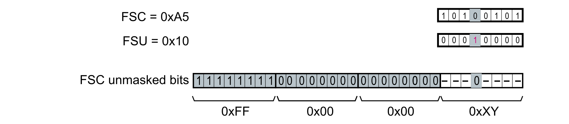
Make sure that each synchronization code has different unmask code to avoid synchronization errors.