AN5156 · Application noteIntroduction to security for STM32 MCUs
Download .pdfOpen in the full document

Firewall

Firewall

The firewall is a hardware protection peripheral controlling the bus transactions and filtering accesses to three particular areas: a code area (flash memory), a volatile data area (SRAM) and a nonvolatile data area (flash memory). The protected code is accessible through a single entry point (the call-gate mechanism explained below). Any attempt to jump and try to execute any of the functions included in the code section without passing through the entry point, generates a system reset.

The firewall is part of the dynamic protections. It must be set at startup (for example by an SB application).

Call gate mechanism
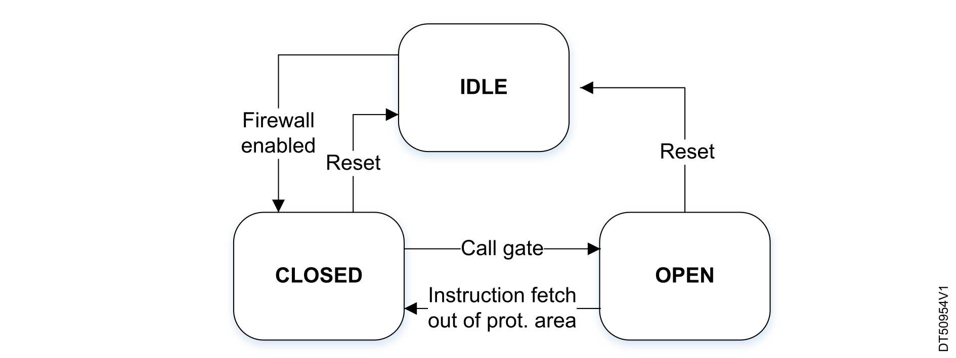
The firewall is opened by calling a 'call-gate' mechanism: a single entry point that must be used to open the gate, and to execute the code protected by the firewall. If the protected code is accessed without passing through the call gate mechanism, then a system reset is generated. If any instruction is fetched outside the protected area, the firewall is closed (see the figure below).
Figure 11. Firewall FSM

Since the only way to respect the call gate sequence is to pass through the single call gate entry point, a mechanism must be provided in order to support application calling multiple firewall-protected functions from unprotected code area (such as encrypt and decrypt functions). A parameter can be used to specify which function to execute (such as CallGate(F1_ID) or CallGate(F2_ID)). According to the parameter, the right function is internally called. This mechanism is represented in the figure below.
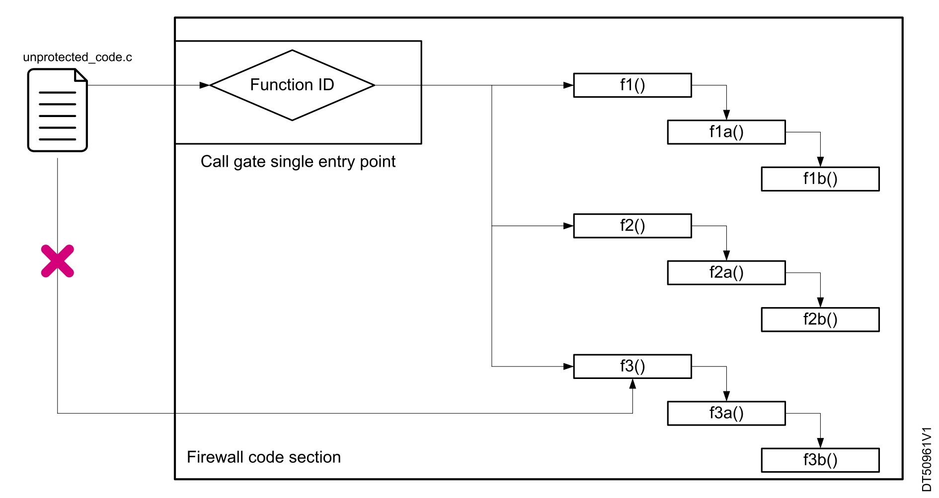
Figure 12. Firewall application example

When to use the firewall

The firewall protects both code and data. The protected code can always be called as long as a call gate mechanism is respected.
Note:

A firewall is available on STM32L0 and STM32L4 devices only. Refer to the application note AN4730 for more details. The firewall functionality is replaced by TrustZone.
Memory protection unit (MPU)

The MPU is a memory protection mechanism that allows specific access rights to be defined for any memory‑mapped resource of the device: flash memory, SRAM, and peripheral registers. This protection is dynamically managed at runtime.

Note:

MPU attributes are only set for CPU access. Other bus master requests (such as DMA) are not filtered by the MPU, and must be deactivated if they are not needed.

Region access attributes

The MPU splits the memory map into several regions, each having its own access attribute. Access right can be set as executable, not executable(XN), read-write (RW), read only (RO), or no access.

Note:

There are other attributes set by the MPU for each region: shareable, cacheable, and bufferable. This application note does not cover the whole complexity of the MPU. This section provides only an introduction and high‑level overview. Refer to applicable programming manual, or to the document AN5156_General-Info.html#concept_vts_yqx_fcb__entry_ilk_brz_qvb.

Privileged and unprivileged modes

On top of the access attribute, the Arm Cortex-M architecture defines two execution modes, allowing a process to run in either privileged or unprivileged mode. For each region, the access attribute can be set independently for each mode.

The table below shows the different cases supported by mixing modes and access attributes.
Table 15. Attributes and access permission managed by MPU
Privileged mode attributeUnprivileged mode attributeDescription
Execute never (XN)1Code execution attribute
No accessNo accessAll accesses generate a permission fault.
RWNo accessAccess from a privileged software only
RWROWritten by an unprivileged software generate a permission fault.
RWRWFull access
RONo accessRead by a privileged software only
RORORead only, by privileged or unprivileged software

The code executed in privileged mode can access additional specific instructions (MRS), and can also access Arm® core peripheral registers (such as NVIC, DWT, or SBC). This is useful for OS kernels or pieces of secure code requiring access to sensitive resources that are otherwise inaccessible to unprivileged firmware.

Secure process isolation strategy

At reset, the privileged mode is the default one for any process. The SB application is then executed in privileged mode. The idea is to isolate secure processes (such as SB, OS kernel, key manager, or SFU) from unsecured or untrusted processes (user applications).
Table 16. Process isolation
Firmware typeModeResources access
Secure firmware (such as SB or OS kernel)PrivilegedFull access
All remaining firmwareUnprivilegedMPU controlled access: no access, RO, RW

An OS kernel can manipulate MPU attributes dynamically to grant access to specific resources depending on the currently running task. Access right can be updated each time the OS switches from one task to another.

When to use the MPU

The MPU is used at runtime to isolate sensitive code, and/or to manage access to resources depending on the process currently executed by the device. This feature is useful especially for advanced embedded operating systems that incorporate security in their design.
Note:

The MPU is available on all STM32 devices except the STM32F0 (see the various programming manuals for more details).

1 XN attribute is set by region, and is valid for both modes. It can be used to avoid SRAM code injection for example.

Resource isolation framework (RIF)

The RIF represents a complex system of address filtering logic that is embedded into the central bus matrix of the device. It can implement various rules for isolation between application code, data, and other resources in a multi-tenant secure OS. The RIF is complementing the TrustZone® system of SAU/IDAU isolation rules, known from other devices.

The configuration is volatile and set during the secure boot, and then fixed in place until the next boot.

In STM32N6, the RIF consists of RIFSC, RISAF, and IAC parts.

For more information, refer to the following wiki article: https://wiki.st.com/stm32mcu/wiki/Security:Resource_Isolation_Framework_(RIF)_overview_for_STM32N6

RAM and integrity secure area firewall (RISAF)

RISAF controls access to a protected address space based on the target address and the bus master that initiates the access. It is controlled by the privileged secure domain.

Peripherals integrated in the MCU that can act as bus masters, such as complex DMA controllers, manage their own RIF alignment. Other resources have their RIF configuration defined by the RIFSC.

The IAC is invoked when an illegal access is detected. It manages the security exception with the secure framework.

Customer key storage (CKS)

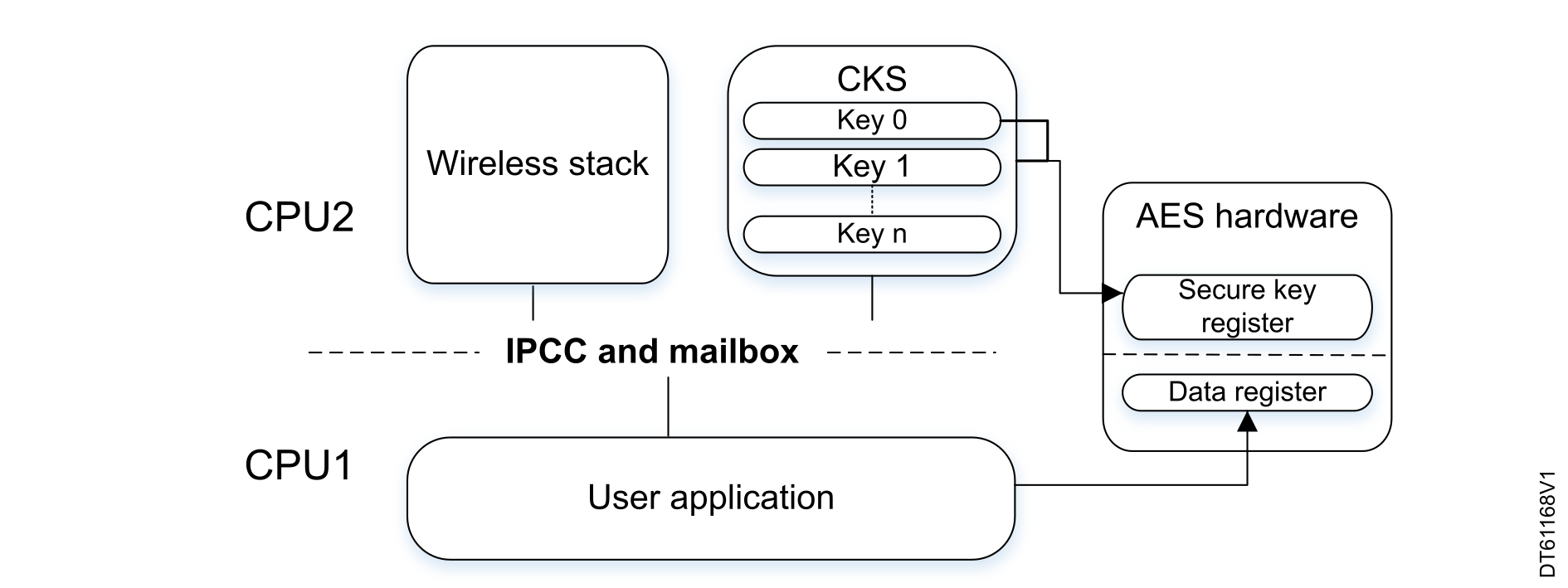
STM32WB series are dual-core devices with one core (CPU1) for user application, and another core (CPU2) dedicated to the wireless real-time aspect execution (either Bluetooth® LE, ZigBee, or thread protocols). The flash memory used by CPU2 is isolated from the CPU1 or external access. Communication between the two cores is ensured by a mailbox and an interprocess channel control hardware block (IPCC).

In addition to the wireless stack execution, the CPU2 offers a secure storage service for cryptographic keys used with a dedicated AES hardware peripheral (see Figure 13 Dual-core architecture with CKS service). The AES key register is accessible only to the CPU2, preventing access to the key by an untrusted process running on the CPU1, or by the debug port.

After the keys have been provisioned inside the secure area, the user application can use them by calling a secure load service with an index referencing the key and no more the key itself.

Figure 13. Dual-core architecture with CKS service

When to use the CKS

The CKS must be used when a user application relies on AES encryption or decryption. Provisioned keys can be stored in a secure area, so that no other internal process or external access can read their value.
Note:

The CKS is available on STM32WB series only.

Option byte keys (OBK)

Option byte keys are secure, nonvolatile storage intended for the protection of keys, specifically storage encryption keys. First introduced on the STM32H5, option byte keys are linked to a multilevel HDP boot progression. Each HDPL value increment closes access to keys used by lower levels, aiding in the implementation of a true secure boot.

The OBK was revised for the STM32H7RS where it is used for the same purpose, but with improved mechanisms of OBK storage management.

OBK is linked to usage of SAES and, in some cases, never allows the actual key to be revealed outside of the hardware storage (hardware keys).

(The OBK is included in STM32H5 and STM32H7R/S)

Antitamper (TAMP)/backup registers (BKP)

The antitamper is a system level protection, used to detect physical tampering attempts on the system. An external tamper event is detected by a level transition on dedicated device pins. Internal tamper sensors can check voltage, temperature, or clock. This event can be used to wake up the core in order to take appropriate actions (such as memory erase or alarm).

This TAMP peripheral includes backup registers with contents preserved by VBAT, along with the real-time clock (RTC). These registers can be reset if a tamper attempt is detected.

On some STM32 devices, this peripheral is known as backup registers (BKP). On recent devices, it has evolved with additional features, such as monotonic counter, or secure section for TrustZone® secure area.

When to use the antitamper

It must be used for system intrusion detection (in consumer products sealed enclosures for example). The monotonic counter is a countermeasure against tampering with the RTC.
Note:

The external tamper detection is available on all STM32 devices. More information about tamper functionality usage is available, for example, in AN4759.