GPDMA overview and instances
The GPDMA controller is used to perform programmable data transfers between memory‑mapped peripherals and/or memories via linked lists, upon the control of an off-loaded CPU. The GPDMA is a dual AHB master and system peripheral. Most of the peripherals and memories are connected to it, giving a lot of flexibility and increasing system performance when data transfers are required. A linked list is a programmed data structure in the memory to prepare each GPDMA channel for chaining and scheduling DMA data transfers.
A GPDMA instance features up to 16 channels.
The following table depicts the GPDMA instances for each STM32 series.
| Product | GPDMA instances |
|---|---|
| STM32H5 | GPDMA1 up to 12 channels + GPDMA2 up to 12 channels |
| STM32H7Rx/7Sx//STM32U5/STM32N6 | GPDMA1 16 channels |
| STM32U3 | GPDMA1 12 channels |
In the STM32H5 series:
- At the hardware level, there are 2 instances of the GPDMA with 8 channels each, named as GPDMA1 and GPDMA2 in the STM32H5 series microcontrollers. The two instances are fully identical and equally connected to the AHB bus matrix, peripherals, memories, and any addressed AHB/APB target. They are also equally connected in terms of input signals like DMA requests or DMA triggers, and in terms of output signals like DMA channels transfer complete signals.
- At the software level, the programmer's view is simplified with a set of 16 GPDMA channels, where GPDMA1 channels are indexed from 0 to 7 and GPDMA2 channels are indexed from 8 to 15. Consequently, in the following sections, the reader must understand that when it is written about a GPDMA channel x with x = 0 to 7, it applies both to the channel x of GPDMA1, and to the channel x + 8 of GPDMA2.
For more details about GPDMA1 and GPDMA2, refer to the STM32H5 reference manual.
GPDMA channel allocation
The user must allocate one channel for a GPDMA transfer. The GPDMA implements a dedicated FIFO to a given GPDMA channel, in order to be able to handle concurrently the GPDMA transfers from the source (read access) and the GPDMA transfers to the destination (write access).
The unit of a FIFO cell is one byte. The FIFO size dictates the maximum DMA burst size (burst length x data width) that the channel can effectively perform. For a given channel, the maximum DMA burst size is half of its FIFO size. Generally the larger the burst is, the better the overall system performances are: higher throughput/bandwidth transfers, lower system bus occupancy.
Given that the system bus is 32-bit word wide, programming a DMA source/destination data width of 32 bits
(S/DDW_LOG2[1:0] in GPDMA_CxTR1) is recommended for a minimized bus utilization.
| Product | Channel number | FIFO size | Addressing mode | |
|---|---|---|---|---|
| STM32H503, STM32H523/533, STM32H562, STM32H563/573, STM32H543/553 | 0 to 3 and 8 to 11 | 8 bytes (2 words) | Linear | |
| 4, 5 and 12, 13 | 32 bytes (8 words) | Linear | ||
| 6, 7 and 14, 15 | 2D | |||
|
STM32H7Rx/7Sx, STM32U5, STM32N6 | 0 to 11 | 8 bytes (2 words) | Linear | |
| 12 to 15 | 32 bytes (8 words) | 2D | ||
| STM32U3 and STM32H5Ex/5Fx | 0 to 7 | 8 bytes (2 words) | Linear | |
| 8 to 9 | 32 bytes (8 words) | Linear | ||
| 10 to 11 | 2D | |||
The following channel allocation is recommended:
- Channels with an 8-byte FIFO must be allocated for AHB/APB peripheral to SRAM transfers (in both ways) unless a 2D addressing is required for the memory, or unless the AHB peripheral supports a burst request
Programming burst as a single word (half of the FIFO size) is then recommended, unless the application requires to handle an 8- or 16-bit data width.
- Channels with 32-byte FIFO must be allocated for memory-to-memory transfers
Programming bursts of 4 words (half of the FIFO size) is then recommended by default, for performances.
These channels are also preferred for:
- Transfers from AHB peripherals supporting a burst request such as OCTOSPI, HASH, and ADC1. Half transfers from/to the peripheral are typically programmed as a burst. The (half) transfer from/to memory is then recommended to be as a 4-word burst.
- Transfers from/to some of the AHB peripherals with higher-bandwidth requirements. The (half) transfer from/to memory is then also recommended to be programmed as a 4-word burst.
Refer to the corresponding product reference manual to know their channel types and the FIFO sizes.
GPDMA port selection
The user must assign one port for the transfer from the source (SAP in GPDMA_CxTR1), and one port for the transfer to the destination (DAP in GPDMA_CxTR1). This assignment is dynamically updated via the next linked-list item and data structure before the execution of the next data transfer.
The bus topology can be summarized as follows (see System performance for more details):
- The GPDMA port 0 is directly connected to APB1 and APB2 peripherals, without crossing to the AHB matrix.
- The default slave of the AHB matrix is:
- AHB1 peripherals for the GPDMA port 0
- SRAM1 for the GPDMA port 1
It is recommended to use the two GPDMA master ports as follows:
- Port 0 is allocated for the (half) transfers from/to a peripheral (whatever it is an AHB or APB peripheral). The other (half) transfer, respectively to/from memory, is allocated to the other port 1. For APB1 and APB2 peripherals, port 0 avoids crossing through the interconnect matrix, and reduces the overall latency on the corresponding channel. This also reduces the AHB bus activity including and behind the interconnect bus matrix.
- Port 1 is allocated for memory-to-memory transfers (especially if accessing SRAM1).
The advantages of using port 0 for peripherals and port 1 for any memory, are:
- Bandwidth balance over the two ports during peripheral to/from memory transfers
- Avoiding bursts to memory from impacting directly the latency of a peripheral access
This is a typical and recommended configuration for performance. The user is of course free to select any port which do have access to the source location, and any port to the destination location.
The GPDMA allocated link port for loading the next linked-list item is defined by the user (LAP in GPDMA_CxCR) at channel level when the channel is not active. A next linked-list item is prepared and resides in the memory. Port 1 is then recommended to be allocated for loading the next linked-list item.
GPDMA channel priority
One priority value is assigned to each (half) transfer for competing versus other concurrent ones. The GPDMA arbiter can then grant and schedule the (half) transfer on one master port. At user level, this is prepared at channel level via PRIO[1:0] in GPDMA_CxCR when the channel is not active.
The GPDMA has two master ports for parallelization of AHB transfers. Simultaneous transfers via the two ports are possible. A GPDMA arbitration occurs for each port as follows:
The GPDMA arbitration phase may introduce 1-cycle clock latency for the GPDMA to generate the AHB address of the granted burst on the allocated master port (see GPDMA burst for more information).
The GPDMA implements a programmable arbitration logic that allows the user to adjust the channel bandwidth and latency according to the following rules:
- The priority of the requested burst transfer is programmable from 0 to 3.
- Requests having the same priority are handled with a round-robin arbitration scheme.
- Priority 3 is recommended for time-sensitive requests because it is handled with a fixed higher priority scheme over priorities 0 to 2.
- The residual bandwidth is shared by requests of priority 0 to 2 by implementing a weighted round-robin allocation for these non time-sensitive channels.
- The different weights are monotonically resulting from the programmed channel priorities, queue 0 having the lowest weight.
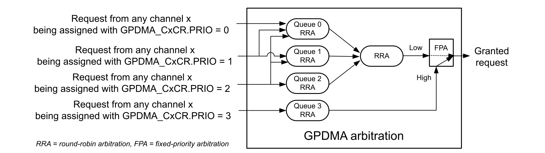
The user needs to assign the correct level of priority to a GPDMA channel on which peripherals/memories are connected, to get an acceptable service quality for this channel:
- No timing error (no peripheral register underrun/overrun) on peripheral side
- Acceptable latency between the data transfer request and the servicing of this request
- Acceptable impact on service quality of the other channels
Channel priorities must be carefully assigned to fit the application timing requirements. A requested FIFO-based transfer of priority 0 to 2 that is ready to be scheduled again on a master port, may be delayed by the round-robin arbiter for the switch, and the execution of up to 7 concurrent (single/burst) transfers of priority 0 to 2. Such a request is also the first preempted by any time-sensitive requested transfers.
A GPDMA channel mapped with a request from a critical timer is typically allocated to the time-sensitive queue, so that the related TIMER registers can be updated with the lowest latency. GPDMA requests from other peripherals may be assigned a priority 2 or 1, and the memory-to-memory transfers may be finally assigned with the lowest priority 0 (best effort traffic). Peripherals mapped to a channel with 8-word FIFO and having a burst capability can be typically assigned to the intermediate priority 1.
This recommendation about channel priority may be tuned to fit specific application requirements (see the reference manual for more details about arbitration and priority).
A data transfer is performed at a linked-list level for a given channel. The user may have chained it with a next data transfer via the same channel, by having programmed a linked-list data structure in memory. Once the data transfer of a given linked-list item (LLI) is completed, the GPDMA reads/fetches automatically the next linked-list data structure, and updates internally its registers, before executing the next data transfer as described. The link‑transfer priority is given by the assigned priority to its channel, in the same way as the data transfer. The link‑transfer consists of a series of 32-bit single reads: up to six single reads for channel with linear‑addressing mode and up to eight single reads for channel with 2D addressing mode. Between every single 32-bit read for the LLI update, the GPDMA takes one extra clock cycle for the arbitration phase.