Current sense amplifiers
A current sense amplifier is a differential amplifier providing an analog output voltage proportional to the current flowing into a load connected on its input.
Current sensing solutions add valuable safety, and protection features to system designs. They provide information to control current in power systems and avoid overheating and short circuits. Current sensing is also an essential part of energy metering to ensure power-efficiency and minimize environmental impact.

Key features
The main features of ST's portfolio of current sensing ICs ensure robustness and application safety:
- -20 to +100 V line monitoring
- Bidirectional or unidirectional current measurement
- Integrated solutions for faster design time and reduced bill of materials
- Integrated EMI filters
- Pin selectable gain
- Shutdown function
- Robust devices that do not require external protection
- Automotive-grade qualified

High-voltage
Tolerance to high voltage ranges and protection mechanisms to handle negative voltage are essential in high-power systems such as batteries in electric vehicles. Our current sense amplifiers can work in high voltage applications avoiding additional external protections components and simplifying the final schematic.
Precision / high-accuracy
Using a precision current sense amplifier allows designers to measure small voltage drops across shunt resistors with minimal error. Small shunt resistors values are necessary to minimize the power dissipation. Thanks to highly accurate current measurements, precision current sense amplifiers offer a better efficiency and thermal performance.
What are the main benefits of a current sense amplifier?
Current sense amplifiers provide several benefits for designers, including the possibility to:
- measure current ranging from a few milli amperes to several hundreds
- perform real-time current measurement in several topologies
- precisely measure current, thanks to an integrated matched resistive gain network
- reduce PCB size thanks to integrated gain resistance
- sustain extended input common mode voltage, far beyond the power supply rail
How does a current sense amplifier work?
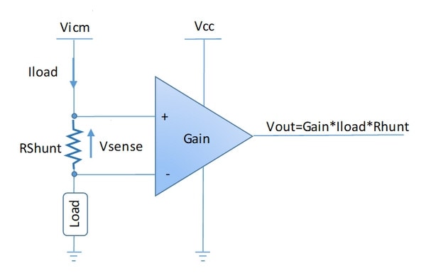
The working principle of a current sensing amplifier is based on Ohm's law. When load current flows through a shunt resistor (Rshunt) present on inputs, it generates a voltage drop called VSENSE. This voltage is generally small to limit power dissipation losses.
VSENSE is then amplified with an internal instrumentation amplifier. The resulting output voltage (VOUT) is a voltage which is proportional to the Ioad current. It can then be processed with an ADC (analog-to-digital converter).
What are the main types of current sense amplifiers?

High-side amplifiers
The current is measured between the supply rail and the load. The DC voltage applied on the input pins can be much higher than the power supply.
Benefits
- Short-to-ground fault detection
- High immunity against ground disturbance
- Current monitored directly from the source
Challenges
- High-input common-mode voltages
- Support fast variation of input common mode voltage
Low-side amplifiers
The current is measured between the load and the ground. The voltage applied on the input pins is close to the ground.
Benefits
- Simple implementation
- Cost-effective solution
- VICM (input common-mode voltage) close to GND (zero-voltage point)
Challenges
- Difficult to detect short-cut to ground
- Multiple output power supply (all current are combined in GND line)
- May disturb the ground voltage seen by the load
Bi-directional VS unidirectional
In some applications, the current can flow into the load in both directions. This is the case for motor control applications used in H-Bridge topologies. In this case, the current sense amplifier must have one additional pin, called VREF. The VREF pin allows designers to set the output reference anywhere within the power supply range. A bidirectional amplifiers can be used as a unidirectional current sense amplifier, setting the reference to one voltage rail.
How to choose the right current sense amplifier for your design?
Define the configuration required for your device
High-side configuration: Select the current sense amplifier depending of the max common mode voltage (VICM) required by the application and its power supply (VCC).
Low-side configuration: Select a current sense amplifier that can work with a common mode voltage close to 0 volts.
Operational amplifiers can be also used, adding 4 external resistors to set the gain. However, the size of the PCB will be larger and accuracy can be lower.Look into the direction of current flows
After defining the configuration required, ask yourself if the current in your application needs to flow in both directions, in order to choose a bidirectional or unidirectional current sensing.
If accurate measurements are needed
Several parameters related to the application must be taken into account. Depending on the current range to be measured and the shunt resistor used, the voltage drop into the shunt resistor can be very small (hundreds of µV). For better accuracy, it is important to consider the error related to offset and accuracy gain.
Featured Videos


Recommended for you


Low- and high-side current sense amplifiers for automotive and industrial applications
STMicroelectronics offers a comprehensive portfolio of current sense amplifiers designed for high accuracy, robustness, and wide operating conditions in automotive, industrial, and telecom applications.
High-voltage, bidirectional current sense amplifiers
Able to sense very low drop voltages as low as 10 mV, our TSC2010 (20 V/V Gain), TSC2011 (60 V/V) and TSC2012 (100 V/V) high-voltage bidirectional current sense amplifiers can sense the current thanks to a shunt resistor over a wide range of common mode voltages from –20 to + 70 V, regardless of the supply voltage. The TSC2010H, TSC2011H and TSC2012H are also available with extended temperature range (-40 to 150 °C); the STEVAL-AETKT1V2 kit can be used to evaluate the devices.
The TSC2020, TSC2021, and TSC2022 enables precision current sensing via a shunt resistor across a wide common-mode voltage range up to 100 V. These devices feature fixed gain options of 20 V/V, 50 V/V, and 100 V/V, supporting bidirectional sensing with very low drop voltages. AEC-Q100 qualified and available in SO-8 and MiniSO-8 packages, they are ideal for current monitoring, overcurrent protection, and feedback loops. The STEVAL-AETKT4V1 evaluation kit facilitates design integration.
Zero-drift current sense amplifiers
Based on a zero-drift architecture that delivers high performance for precision current sensing, the TSC210 / TSC211 / TSC212 / TSC213 / TSC214 / TSC215 feature exceptional precision and low offset while offering different gain. They can operate over a broad supply voltage range, from 2.7 to 26 V, and support temperatures ranging from -40 to 125 °C, making them ideal for industrial and automotive applications. The STEVAL-AETKT2V1 evaluation board supports engineers in their design.
Current sense amplifiers with integrated comparator and reference
 The TSC200, TSC201, and TSC202 provide analog voltage output with integrated open-drain comparators featuring output latches and a 0.6 V internal voltage reference. These AEC-Q100 qualified amplifiers support common-mode voltages from -20 V to +80 V and offer gains of 20 V/V, 50 V/V, and 100 V/V respectively, making them well-suited for overcurrent protection and system monitoring. To support developers in their designs, the STEVAL-AETKT3V1 evaluation kit is available
High-precision current sense amplifier with enhanced PWM rejection
The TSC240 is a high-side and low-side bidirectional zero-drift current sense amplifier designed for accurate current measurement with enhanced PWM noise rejection. It supports sensing current through a shunt resistor across a wide common-mode voltage range from –4 to +100 V, independent of the supply voltage. Featuring a fixed gain of 20 V/V, the TSC240 detects very low voltage drops while minimizing measurement errors.
Operating over a broad supply voltage range of 2.7 to 5.5 V and an industrial temperature range of –40 to +125 °C, this amplifier is ideal for precision current measurement, overcurrent protection, current monitoring, and feedback control applications. Its key features include excellent DC common-mode rejection ratio (132 dB), low gain error (0.20% max), minimal offset voltage (±20 µV max), and low quiescent current (2.4 mA max).
AEC-Q100 qualified and available in SO8 and TSSOP8 packages, the TSC240 is suitable for motor controls, solenoid and valve controls, power management, industrial process control, as well as for automotive applications and telecom equipment.
eDesignSuite
eDesignSuite is a comprehensive set of easy-to-use design-aid utilities ready to help you streamline the system development process with a wide range of ST products.


Power Management Design Center
Thermal-electrical Simulators for Components
Signal Conditioning Design Tool
NFC/RFID Calculators
Power Management Design Center

Power Supply Design Tool
Power Management Design Center

LED Lighting Design Tool
Power Management Design Center

Digital Power Workbench
Power Management Design Center

Power Tree Designer
Thermal-electrical Simulators for Components

STPOWER Studio
Thermal-electrical Simulators for Components
PCB Thermal Simulator
Thermal-electrical Simulators for Components

AC Switches Simulator
Thermal-electrical Simulators for Components

Rectifier Diodes Simulator
Thermal-electrical Simulators for Components

Twister Sim
Thermal-electrical Simulators for Components

TVS Simulator
Thermal-electrical Simulators for Components

Estimate
Signal Conditioning Design Tool

Active Filters
Signal Conditioning Design Tool

Comparators
Signal Conditioning Design Tool

Low side Current Sensing
Signal Conditioning Design Tool

High side Current Sensing
NFC/RFID Calculators

NFC Inductance
NFC/RFID Calculators

UHF Link Budget
NFC/RFID Calculators
