AN4759 · Application noteIntroduction to using the hardware real-time clock (RTC) and the tamper management unit (TAMP) for STM32 MCUs
Download .pdfOpen in the full document

RTC calendar

RTC calendar

A calendar keeps track of the time (hours, minutes and seconds) and date (day, week, month, year). The RTC calendar offers the following features to easily configure and display the calendar data fields:
  • Calendar with subseconds (not programmable), seconds, minutes, hours (12 h/24 h format), day of the week (day), day of the month (date), month, year
  • Calendar in BCD format
  • Automatic management of 28-, 29- (leap year), 30-, and 31-day months
  • Daylight saving time adjustment programmable by software
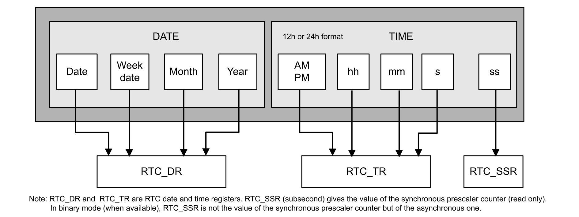
Figure 1. RTC calendar fields

Software calendar

A software calendar is a software counter (usually 32-bit long) that represents the number of seconds. The software routines convert the counter value to hours, minutes, day of the month, day of the week, month and year. This data can be converted to BCD format and displayed on a standard LCD. Conversion routines use a significant program memory space and are CPU-time consuming, that may be critical in certain real-time applications.

RTC hardware calendar

When using the RTC calendar, the software conversion routines are no longer needed because their functions are performed by hardware.

The STM32 RTC calendar is provided in BCD format. This avoids binary to BCD software conversion routines, that save system resources.

Figure 2. Example of calendar displayed on an LCD

Initialize the calendar

the table below describes the steps required to correctly configure the calendar time and date.

Table 6. Steps to initialize the calendar
StepWhatHowComments
1Disable the RTC registers write protection.Write 0xCA and then 0x53 into RTC_WPR.RTC registers can be modified.
2Enter initialization mode.Set INIT = 1 in RTC_ISR (RTC2)/RTC_ICSR (RTC3) registerThe calendar counter is stopped to allow its update.
3Wait for the confirmation of initialization mode (clock synchronization).Poll INITF bit of in RTC_ISR (RTC2)/RTC_ICSR (RTC3) until it is set.
  • For RTC2: It takes around two RTCCLK clock cycles due to clock synchronization.
  • For RTC3: If LPCAL = 0, INITF is set around two RTCLK cycles after INIT is set. If LPCAL = 1, INITF is set up to two ck_apre cycles after INIT is set.
4Program the prescaler values (if needed).In RTC_PRER, write first the synchronous value, and then write the asynchronous value.

For RTC3, program also BIN and BCDU in RTC_ICSR, if in binary or mixed mode.

By default (in BCD mode for RTC3), RTC_PRER is initialized to provide 1 Hz to the calendar unit (when RTCCLK = 32768 Hz).
5Load time and date values in the shadow registers.Set RTC_TR and RTC_DR.-
6Configure the time format (12 h or 24 h)Set FMT bit in RTC_CR.If FMT = 0, the format is 24 hour/day.

If FMT = 1, the format is 12 h am/pm.

7Exit initialization mode.Clear INIT in RTC_ISR (RTC2)/RTC_ICSR (RTC3).For RTC2: The current calendar counter is automatically loaded and the counting restarts after four RTCCLK clock cycles.

For RTC3: If LPCAL = 0, the counting restarts after four RTCCLK clock cycles. If LPCAL = 1, the counting restarts after up to two RTCCLK + 1 ck_apre cycles.

8Enable write protection of the RTC registers. Write 0xFF into RTC_WPR.The RTC registers can no longer be modified.

RTC clock configuration

RTC clock source

The RTC calendar can be driven by one of three possible clock sources LSE, LSI or HSE.

If the HSE is selected, a prescaler must be selected. The user can refer to the product reference manual to know its possible values and configurations.

Moreover, the choice of the RTC clock source is done thanks to the RTCSEL[1:0] in a RCC register. This register depends on the product and this information can also be found in the product reference manual.

How to adjust the RTC calendar clock

The RTC features several prescalers that allow delivering a 1 Hz clock to the calendar unit, regardless of the clock source.

For the RTC3 type, the BCD or mixed mode is considered. In binary mode (available only on RTC3), the calendar is not functional.
Figure 3. Prescalers from RTC clock source to calendar unit
Important:

The calendar unit is linked to ck_spre but belongs to the ck_apre (asynchronous prescaler) clock domain. The choice of ck_apre can help to optimize power consumption.

The formula to calculate ck_spre is:

c k _ s p r e ⁢ =   R T C C L K ( P R E D I V _ A ⁢ + 1 ) × ( P R E D I V _ S + 1 )
where:
  • RTCCLK is any clock source (HSE_RTC, LSE or LSI).
  • PREDIV_A is any number from 1 to 127.
  • PREDIV_S is any number from 0 to 32767.

The table below shows several ways to obtain the calendar clock ck_spre = 1 Hz.

Other PREDIV_A[6:0]/PREDIV_S[14:0] values are possible. The user must always prefer the combination where PREDIV_A[6:0] is the highest for the needed accuracy and for lower consumption.
Table 7. Calendar clock ck_spre= 1 Hz with various clock source
RTCCLK clock source Prescalers
PREDIV_A[6:0] PREDIV_S[14:0]
HSE_RTC = 1 MHz 124 (div 125) 7999 (div 8000)
LSE = 32.768 kHz 127 (div 128) 255 (div 256)
LSI = 32 kHz 127 (div 128) 249 (div 250)
LSI = 37 kHz 124 (div 125) 295 (div 296)
LSI = 40 kHz 127 (div 128) 311 (div 312)

Calendar firmware examples

The RTC comes with a set of example projects so that the user can quickly become familiar with this peripheral. Refer to the X-CUBE-RTC Expansion Package for a complete projects list.

For example, the user can find the following projects concerning calendar:
  • For the NUCLEO-L412RB-P equipped with an RTC3:
    • STM32Cube_FW_L4_Vx.y.z\Projects\NUCLEO-L412RB-P\Examples\RTC\RTC_Calendar
    • STM32Cube_FW_L4_Vx.y.z\Projects\NUCLEO-L412RB-P\Examples_LL\RTC\RTC_Calendar
  • For the P-NUCLEO-WB55 equipped with an RTC2:
    • STM32Cube_FW_WB_Vx.y.z\Projects\P‑NUCLEO‑WB55.Nucleo\ Examples_LL\RTC\RTC_Calendar_Init

If one example is not available in the X-CUBE-RTC for a given STM32 MCU, the user can adapt it.

Binary and mixed modes (RTC3 only)

For the RTC3 type, a binary mode is available. In this mode, the time and date BCD calendar are disabled but the RTC sub‑second register (SSR) is extended to 32 bits (16 bits in normal mode) and is used as a binary down-counter.

Thanks to this feature, a 32-bit counter is available in low-power mode (modes compatibilities are the same than for the other RTC features) and a BCD-to-binary conversion is no more needed (when required by an application).

The binary mode implementation is simple:
  1. Initialization: Set INIT = 1 in RTC_ICSR and wait for INITF to be set.
  2. Define the asynchronous prescaler value in RTC_PRER to clock the binary counter.
  3. Set BIN[1:0] = 01 in RTC_ICSR: the RTC_SSR register is initialized to 0xFFFF FFFF.
  4. After exiting initialization (INIT bit cleared), the counter start to count down from the RTC_SSR initial value.
  5. The counter is clocked by the RTC asynchronous prescaler output. When it reaches 0, it is reloaded with 0xFFFF FFFF.

In binary mode, the RTC_ALRABINR register is used to program the subsecond field of the alarm.

The mixed mode (also offered by RTC3 type) allows both the 32-bit binary down-counter and the BCD calendar. In this mode, the user can choose when the calendar is incremented by 1 second with BCDU[2:0] in RTC_ICSR. These bits code how many least significant bits from SSR (subsecond register) need to be at 0 for the calendar to be incremented by 1 second.

A shadow register exists for RTC_SSR. It can be bypassed when BYPSHAD = 1 in RTC_CR. See RTC clock synchronization for more details on BYPSHAD use and associated cautions to take.