STM32L4 API and smooth digital calibration application example
STM32L4 API and smooth digital calibration application example
STM32CubeL4 firmware libraries for smooth calibration
The timer peripheral comes with:
A firmware driver API abstracting the timer features for the end-user
Refer to stm32l4xx_hal_tim.c and stm32l4xx_hal_tim_ex.c files in \STM32Cube_FW_L4_Vx.y.z\Drivers\STM32L4xx_HAL_Driver\
A set of example projects in \STM32Cube_FW_L4_Vx.y.z\Projects\STM32L476RG-Nucleo\Examples\TIM
The RTC comes with:
A firmware driver API abstracting the RTC features for the end-user
Refer to stm32l4xx_hal_rtc.c and stm32l4xx_hal_rtc_ex.c files in \STM32Cube_FW_L4_Vx.y.z\Drivers\STM32L4xx_HAL_Driver\
A set of example projects in \STM32Cube_FW_L4_Vx.y.z\Projects\STM32L476RG-Nucleo\Examples\RTC
X-CUBE-RTC for smooth calibration
X-CUBE-RTC shows an implementation of the smooth digital calibration feature of the RTC (using also the GPTIMER HAL API).
In this example, the RTC_CLK is smoothly calibrated based on an external 1 Hz reference (STM32CubeExpansion_AN4759_RTC_STM32L_Vx.y.z\Projects\STM32L476RG_Nucleo\RTC_SmoothCalib).
The firmware implements:
A GPTIMER (general-purpose timer) in Master mode using channel 1 in output compare mode (and using an external trigger clock)
A GPTIMER in Master mode using channel 1 in input capture mode and channel 2 in output compare mode
This timer is also configured to use the LSE clock thanks to the TIM option register.
The RTC with the CALR register programming
GPIOs to connect the input 1 Hz reference clock and the “corrected” RTC_OUT_CALIB clock
Smooth calibration application example (STM32L4)
Hardware setup
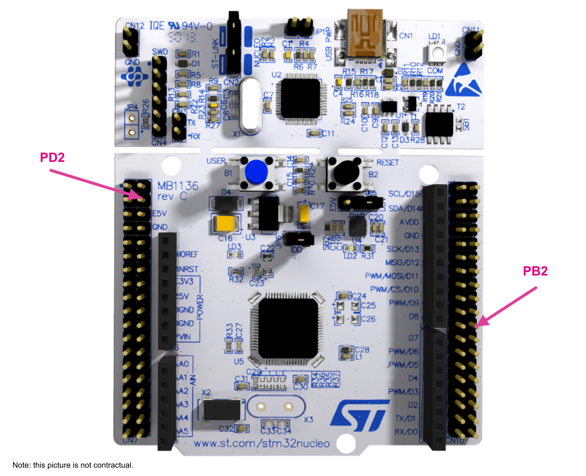
In order to use the application example project, the user needs a STM32L476RG Nucleo board (NUCLEO‑L476RG).Figure 20. NUCLEO-L476RG board
Supply the board using the USB cable and perform the following actions:
Connect PD2 to a signal generator driving 1 Hz clock with 3.3 V amplitude. It is advised to control the generated frequency at few ppm.
Connect PB2 to an oscilloscope (the accuracy of the frequency measurement is ideally in the range of 1 ppm).
Software setup
Open the project under the user favorite IDE. For IAR Embedded Workbench, open the RTC_SmothCalib.eww file. For MDK-ARM, open the RTC_SmoothCalib.uvprojx file. For SW4STM32, open the SW4STM32 toolchain, browse to the SW4STM32 workspace directory, select and import the project RTC_SmoothCalib.
Compile and launch the debug session. It loads the program in the internal Flash memory and executes it.
After a maximum of 64 seconds, make a frequency measurement of the CALIB_OUT clock on PB2. The user gets a frequency accurate at 1 ppm compared to the 1 Hz reference clock sent on PD2.
The user can then modify the PD2 clock by few ppm, wait 64 seconds, and check that the PB2 clock has been changed accordingly.
Under debugger, the user can monitor the evolution of the CALR register fields (CALP and CALM).
Smooth calibration application principle
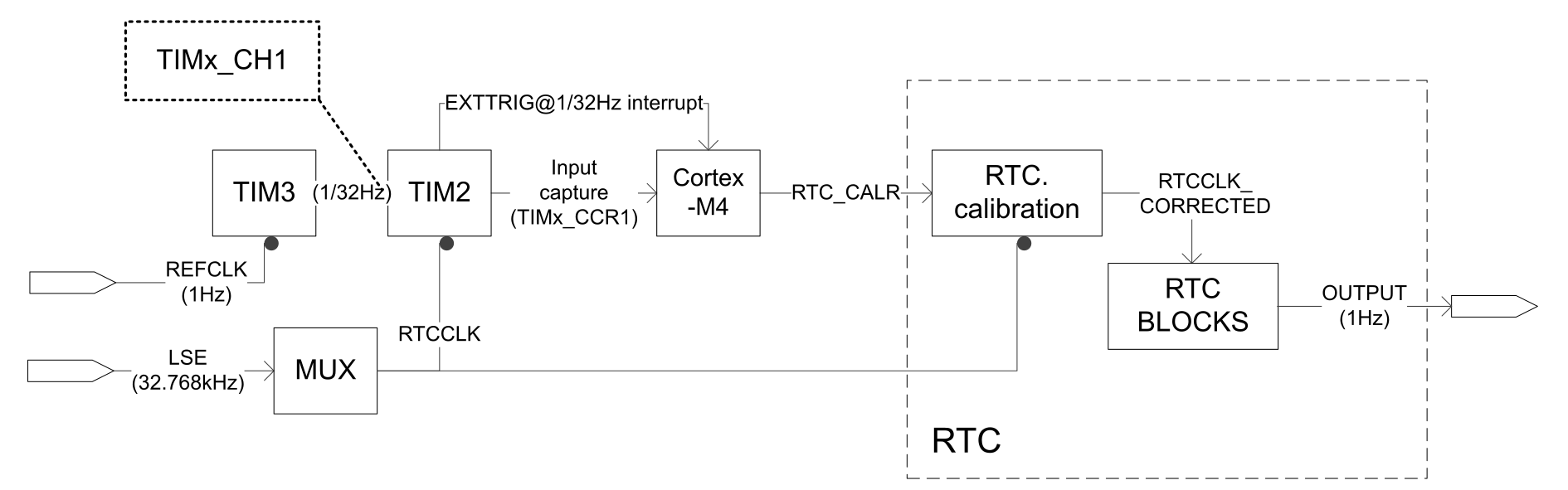
The figure below provides a block diagram of the smooth digital calibration application. Figure 21. Block diagram of a smooth digital calibration
This application is based on the following steps:
A 1 Hz reference clock is connected to TIM3 through the PD2 GPIO.
TIM3 is configured to generate a rising edge after 32 x 1 Hz reference rising edges. This gives an event every 32 s.
TIM2 is configured to increment its counter on CLK_RTC, to get the counter value on the rising edge generated by TIM3, and to store it in TIM2_CCR1 register. Then TIM2 counter is reset.
The Cortex-M4 core gets the TIM2_CCR1 value, compares it with the number of CLK_RTC cycles expected in 32 s and processes the comparison results to update the CALP and CALM[8:0] in RTC_CALR.
The calibration is continuous.
Run time observations
The following steps are needed to check the correct functionality:
Modify the 1 Hz reference clock (for instance by forcing 1.0001 Hz).
Wait 2 x 32 s.
Measure the output frequency. Depending on the accuracy of the generator and the measurement device used, the user can see around 1 ppm accuracy.
The user can also monitor in Debug mode:
CALP and CALM[8:0] in RTC_CALR
TIM2_CCR1 register (contains the number of CLK_RTC cycles within a 32 s window)
Porting suggestions
The software example expects that the TIM2 is more than 20 bit, 32 bit in case of L476RB. With products featuring only 16-bit timers it is recommended to keep track of 16-bit timer overflows using the software and perform the calibration with 16-th overflow to compensate for the missing 4 bits.
STM32L0 API and tampering detection application example
STM32CubeL0 firmware libraries
The RTC comes with:
A firmware driver API abstracting RTC features for the end-user
Refer to stm32l0xx_hal_rtc.c and stm32l0xx_hal_rtc_ex.c files in \STM32Cube_FW_L0_Vx.y.z\Drivers\STM32L0xx_HAL_Driver\
A set of example projects in \STM32Cube_FW_L0_Vx.y.z\Projects\STM32L053R8-Nucleo\Examples\RTC
X-CUBE-RTC for tamper detection
X-CUBE-RTC shows an example where a real-time clock must be maintained alive while using as less power as possible (STM32CubeExpansion_AN4759_RTC_STM32L_Vx.y.z\Projects\STM32L053R8-Nucleo\RTC_Tamper.
The firmware implements:
A few hints order to ensure a low current consumption
A display in the debugger (date and time, timestamp date and time) and on a single LED (power-up events, reset events, tamper events, error)
Tampering detection capability
The ability to timestamp the tampering event
The ability to erase the backup registers that may contain sensitive data upon tamper detection
In order to use the application example project, the user needs a STM32L053R8 Nucleo board (NUCLEO-L053R8).Figure 22. NUCLEO-L053R8 board
Supply the board using the USB cable. In this example, the B1 push button is used to simulate the external tamper event. The user can observe the software "private variables" on LED LD2 and CN5 pin 6 (SCK/D13). Details regarding the LED LD2 behavior are available in main.c file.Figure 23. LED LD2 behavior
Software setup
Open the project under the user favorite IDE (integrated development environment). For IAR Embedded Workbench, open the project.eww file. For Keil MDK-ARM, open the project.uvprojx file, compile and launch the debug session. For SW4STM32, open the SW4STM32 toolchain, browse to the SW4STM32 workspace directory, select and import the project RTC_Tamper.
Compile and launch the debug session. This loads the program in the internal Flash memory and executes it.
In IAR Embedded Workbench debug session, the user can view the calendar and tamper event timestamp (time and date) by opening a Live watch window (View\Live watch) and observe the following global variables:
aShowTime
aShowDate
aShowTimeStampTime
aShowTimeStampDate
The user can add and follow these private variables with:
LED1_Green_Tamper_event_detected
LED2_Red_Power_On_Reset_occurred
LED3_Red_Error
LED4_Blue_Reset_occurred
The same observation can be done using MDK-ARM development tools. To open the Watch1 window, do View\Watch Windows\Watch1.
LED meaning
Only one LED (LD2) is available on the STM32L053R8 Nucleo board. To match with the STM32L4 examples, described in Tamper detection application example (STM32L4), LED1, LED2, LED3 and LED4 are replaced by the following integers:
uint32_t LED1_Green_Tamper_event_detected: set when tamper1 event is detected (LED1 equivalent)
uint32_t LED2_Red_Power_On_Reset_occurred: set when power-on reset is detected (LED2 equivalent)
uint32_t LED3_Red_Error: set in errors cases (LED3 equivalent)
uint32_t LED4_Blue_Reset_occurred: set when reset is detected (B2 black push button, LED4 equivalent)
The user can observe these private variables using the live watch feature in the debugger, or on LED LD2 and CN5 pin 6 (SCK/D13). Regarding the LED LD2 behavior, see details in main.c file.
Tampering detection during normal operation
Step 1
A power-on reset can be generated by disconnecting/connecting the USB cable on CN1.
Table 18. Tamper detection status when a power-on reset is detected
Meaning
Status
LD2 blink
LED1_Green_Tamper_event_detected
0
OFF
LED2_Red_Power_On_Reset_occurred
1
ON
LED3_Red_Error
0
OFF
LED4_Blue_Reset_occurred
1
ON
Step 2
Push B1 to simulate a tamper event.
Table 19. Tamper detection status when a tamper event is detected (after a power-on reset)
Meaning
Status
LD2 blink
LED1_Green_Tamper_event_detected
1
ON
LED2_Red_Power_On_Reset_occurred
1
ON
LED3_Red_Error
0
OFF
LED4_Blue_Reset_occurred
1
ON
Step 3
Push B2 to simulate a reset.
Table 20. Tamper detection status when a reset is detected
Meaning
Status
LD2 blink
LED1_Green_Tamper_event_detected
0
OFF
LED2_Red_Power_On_Reset_occurred
0
OFF
LED3_Red_Error
0
OFF
LED4_Blue_Reset_occurred
1
ON
Step 4
Push B1 to simulate a tamper event.
Table 21. Tamper detection status when a tamper event is detected (after a reset)