STM32L5 API and smooth digital calibration application example
STM32L5 API and smooth digital calibration application example
STM32CubeL5 firmware libraries for smooth calibration application
The timer peripheral (TIM) comes with:
A firmware driver API abstracting TIM features for the end-user
Refer to stm32l5xx_hal_tim.c and stm32l5xx_hal_tim_ex.c files in \STM32Cube_FW_L5_Vx.y.z\Drivers\STM32L5xx_HAL_Driver\
A set of example projects in \STM32Cube_FW_L5_Vx.y.z\Projects\ NUCLEO-L552ZE-Q\Examples\TIM
The RTC comes with:
A firmware driver API abstracting TIM features for the end-user
Refer to stm32l5xx_hal_rtc.c and stm32l5xx_hal_rtc_ex.c files in \STM32Cube_FW_L5_Vx.y.z\Drivers\STM32L5xx_HAL_Driver\
A set of example projects in \STM32Cube_FW_L5_Vx.y.z\Projects\ NUCLEO-L552ZE-Q\Examples\RTC
X-CUBE-RTC for smooth calibration
X-CUBE-RTC shows an implementation of the smooth digital calibration feature of the RTC (using also the GPTIMER HAL API).
In this example, the RTC_CLK is smoothly calibrated based on an external 1 Hz reference (STM32CubeExpansion_AN4759_RTC_STM32L_Vx.y.z\Projects\NUCLEO-L552ZE-Q\RTC_SmoothCalib).
The firmware implements:
A GPTIMER (general-purpose timer) in Master mode using channel 1 in output compare mode (and using an external trigger clock)
A GPTIMER in Master mode using channel 1 in input capture mode and channel 2 in output compare mode
This timer is also configured to use the LSE clock thanks to the TIM option register.
The RTC with the CALR register programming
GPIOs to connect the input 1 Hz reference clock and the “corrected” RTC_OUT_CALIB clock
Smooth calibration application example (STM32L5)
Hardware setup
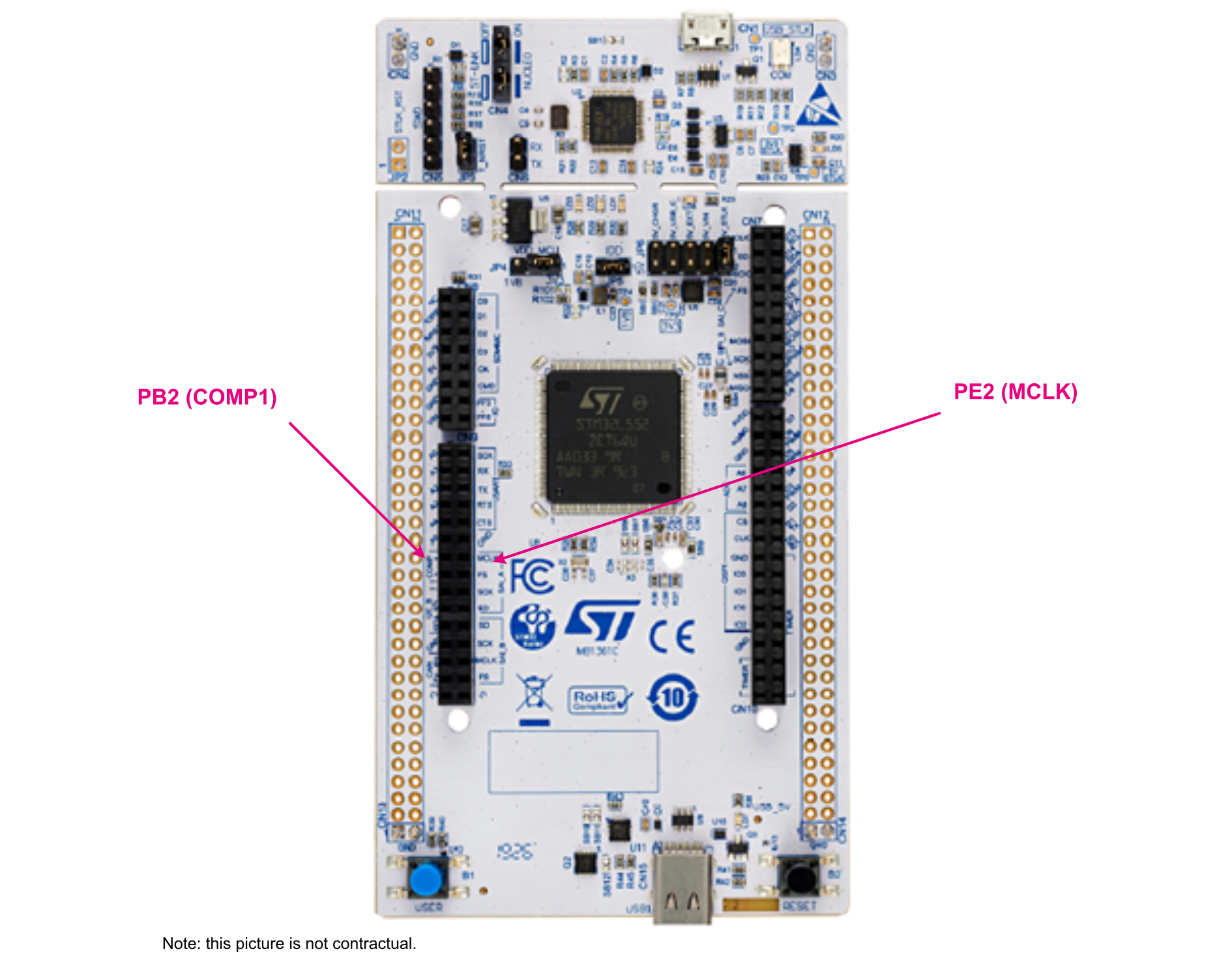
In order to use the application example project, the user needs a STM32L552ZE-Q Nucleo board (NUCLEO‑L552ZE-Q)Figure 24. NUCLEO-L552ZE-Q board
Supply the board using the USB cable and perform the following actions:
Connect PE2 to a signal generator driving 1 Hz clock with 3.3 V amplitude. It is advised to control the generated frequency at few ppm.
Connect PB2 to an oscilloscope (the accuracy of the frequency measurement is ideally in the range of 1 ppm).
Software setup
Open the project under the user favorite IDE. For IAR Embedded Workbench, open the RTC_SmoothCalib.eww file. For MDK-ARM, open the RTC_SmoothCalib.uvprojx file. For STM32CubeIDE, open the .cproject file.
Compile and launch the debug session. It loads the program in the internal Flash memory and executes it.
After a maximum of 64 seconds, make a frequency measurement of the CALIB_OUT clock on PB2. The user gets a frequency accurate at 1 ppm compared to the 1 Hz reference clock sent on PE2.
The user can then modify the PE2 clock by few ppm, wait 64 seconds, and check that the PB2 clock has been changed accordingly.
Under debugger, the user can monitor the evolution of the CALR register fields (CALP and CALM).
A 1 Hz reference clock is connected to TIM3 through the PE2 GPIO.
TIM3 is configured to generate a rising edge after 32 x 1 Hz reference rising edges. This gives an event every 32 s.
TIM2 is configured to increment its counter on CLK_RTC, to get the counter value on the rising edge generated by TIM3, and to store it in TIM2_CCR1 register. Then, TIM2 counter is reset.
The Cortex-M33 core gets the TIM2_CCR1 value, compares it with the number of CLK_RTC cycles expected in 32 s and processes the comparison results to update the CALP and CALM[8:0] in RTC_CALR.
The calibration is continuous.
Run time observations
The following steps are needed to check the correct functionality:
Modify the 1 Hz reference clock (for instance by forcing 1.0001 Hz).
Wait 2 x 32 s.
Measure the output frequency. Depending on the accuracy of the generator and the measurement device used, the user can see around 1 ppm accuracy.
The user can also monitor in Debug mode:
CALP and CALM[8:0] in RTC_CALR
TIM2_CCR1 register (contains the number of CLK_RTC cycles within a 32 s window)
STM32L5 API and synchronization application example
TIM1 in Master mode with update interrupt activated to generate an interruption each second. It is configured to exploit an external 16 MHz signal thanks to the bypass of HSE clock. A PLL is also used for the timer to be clocked by a 100 MHz signal.
the RTC with the SHIFTR register programming
GPIO: RTC_OUT CALIB to check if the RTC 1 Hz output frequency is really 1 Hz (synchronization does not affect the RTC_OUT CALIB output but this signal needs to be as close as possible to 1 Hz for the synchronization to work)
The user LED2 (PB7) is used to visualize the 1-s period and the good working of the application.
Synchronization application example (STM32L5)
Hardware setup
In order to use the application example project, the user needs a STM32L552ZE-Q Nucleo board (NUCLEO‑L552ZE-Q). Supply the board using the USB cable.
The TIM1 clock source is HSE. However, the X3 crystal associated to HSE is not implemented by default on the Nucleo board. Then, the application exploits the HSE bypass functionality of the STM32 to input an external 16 MHz signal to substitute the crystal (for this feature, the user must have SB142 ON, SB145 ON, SB143 OFF, SB6 OFF, SB7 OFF). This signal must be generated on PH0 (position 29 on CN11, right next to the connection A1 of CN9).
The internal HSI clock is not used since it is less precise than the LSE oscillator that clocks the RTC. Moreover, the HSE external 16 MHz signal must be more precise than the LSE.
The user can check that the RTC prescalers are well configured for the board by verifying a 1 Hz signal is output on PB2 (RTC_OUT CALIB output).
Software setup
Open the project under the user favorite IDE. For IAR Embedded Workbench, open the RTC_Synchronization.eww file. For MDK-ARM, open the RTC_Synchronization.uvprojx file. For STM32CubeIDE, open the .cproject file.
Compile and launch the debug session. It loads the program in the internal Flash memory and executes it.
Synchronization application principle
This application is based on the following steps:
TIM1 is configured and launched to generate an interruption each second (APB2 timer clock = 100 MHz).
RTC is configured and launched including its calendar (RTC clock = LSE).
The 1-second period counted by the TIM1 interruptions allows a more precise time base than with RTC (the external HSE bypass signal must be more precise than LSE).
With this time base and thanks to the subsecond register, the advance/delay of the RTC clock can be analysed on the TIM1 1-second period.
With the SHIFTR register, this advance or delay is compensated.
The synchronization is continuous.
Run time observations
The following steps are needed to check the correct functionality:
Set the SYNCHRO_ACTIVATED to 0 and observe the time_elapsed variable deriving (getting away from 255/1 sec). The user can monitor it in Debug mode.
Set the SYNCHRO_ACTIVATED to 1 and observe that the time_elapsed variable derivation is less important.
time_elapsed embodies the 1-second period measured for RTC.
Note:
A typical quartz has an uncertainty of 53 s/month. This uncertainty must be attenuated with synchronization that is efficient if the clock used (external 16 MHz in the present case) has a better uncertainty. Using an HSE X3 crystal is not so efficient if the LSE crystal has the same uncertainty.
To check that the application runs properly, the user can also visualize the user LED2 blinking each second and the RTC_OUT CALIB output on the PB2 pin (these two observations do not witness the efficiency of the synchronization but can help the user to understand what happens).