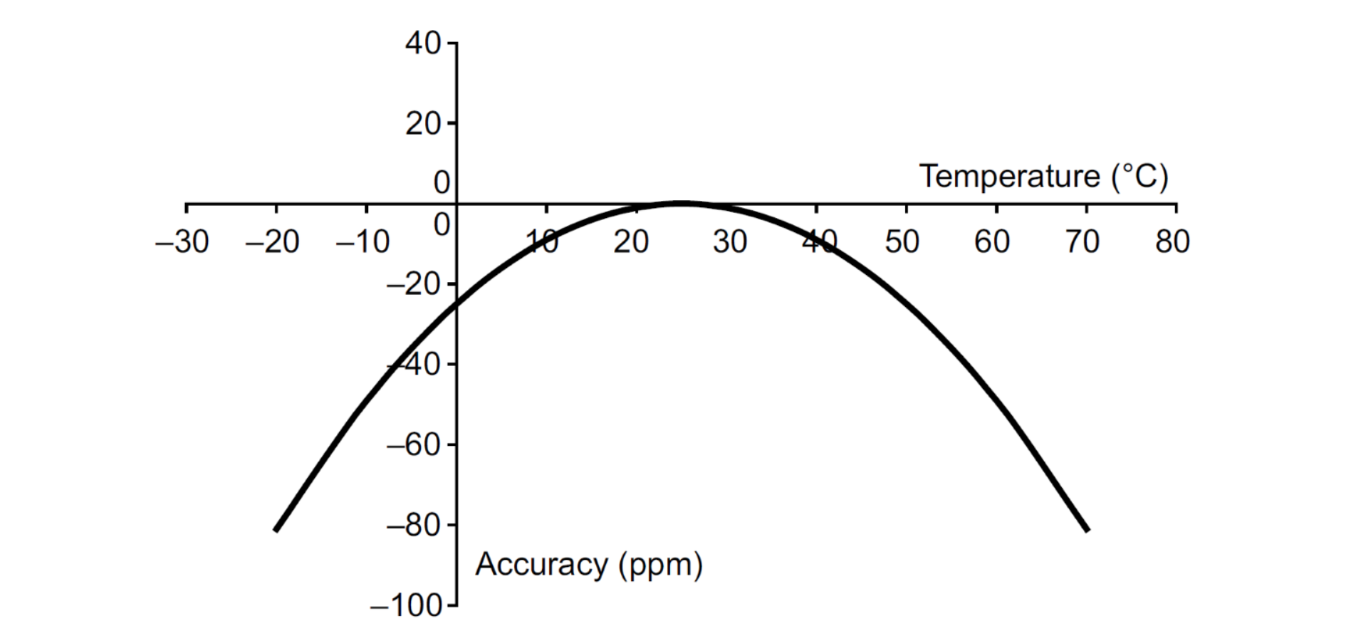
The “quartz-accurate” term describes the accuracy of many time-keeping functions. The quartz oscillators provide a far superior accuracy versus other conventional oscillator designs, but they are not perfect, as the quartz crystals are sensitive to temperature variations. Figure 8 Typical crystal accuracy plotted against temperature shows the relationship between accuracy (acc), temperature (T) and curvature (K) for a typical 32.768 kHz crystal, following the general formula:
where To = 25 °C ± 5 °C and K = –0.032 ppm/°C2.
Note:
The K variable is crystal-dependent. The value indicated here is for the crystal mounted on the STM32L476RG-Nucleo board. Refer to the crystal manufacturer for more details on this parameter.
The clocks used in most applications require a high degree of accuracy, and there are several factors involved in achieving this accuracy.
Two major approaches exist to compensate an oscillation frequency deviation of an oscillator when the generated signal is used to clock a time-keeping logic:
Analog approach
The oscillator is built with embedded capacitor banks on both input and output of the oscillator. To adjust the oscillation frequency, the software needs to configure the oscillator to switch on or off some of the embedded load capacitors to adjust the overall load capacitance seen by the crystal resonator.
Note that the two external load capacitors are always needed even with this kind of oscillators. The two external load capacitors make the dominant part of the load capacitance of the crystal resonator. The oscillator embedded capacitor banks are only intended to compensate for the capacitance value dispersion of the two external load capacitors; or to compensate for the temperature variation. This approach suffers from most of drawbacks that generally analog circuits suffer from, such as relatively important value dispersion from one chip to another.
Digital approach
The oscillation frequency deviation is not compensated at oscillator level. The compensation is made at time-keeping logic/function level. The time-keeping logic either adds or removes few clock cycles to/from the deviating clock signal that feeds its counter. The main advantage of this approach is the deterministic compensation effect from one device to another. This approach is adopted to compensate the LSE oscillation frequency deviation when LSE is used to clock the RTC. The RTC is built with a dedicated register to configure the number of clock cycles to add or remove from the feeding clock signal.
Figure 8. Typical crystal accuracy plotted against temperature
RTC calibration methodology
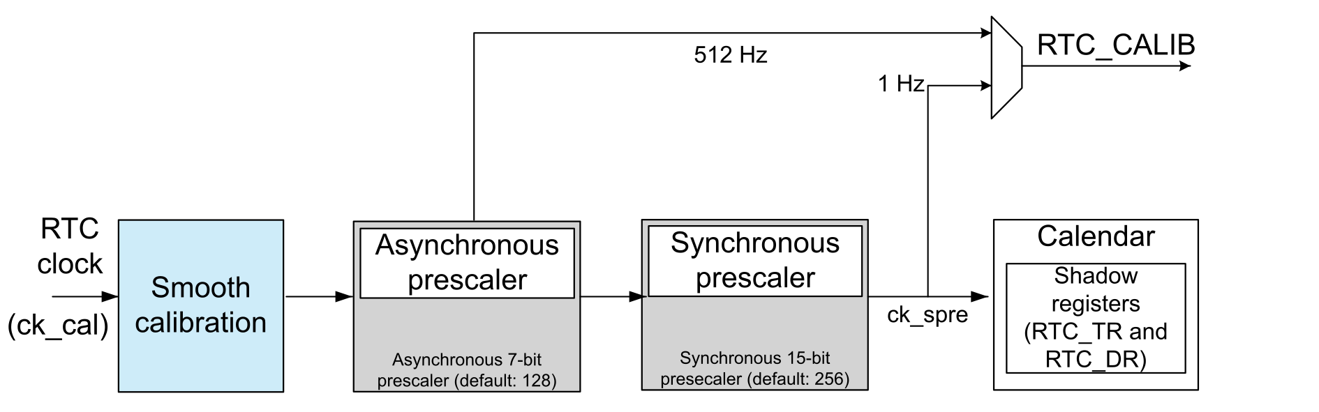
The RTC clock frequency can be corrected using a series of small adjustments by adding or subtracting individual ck_cal (smooth calibration clock) pulses.
For RTC2 type, ck_cal is always RTCCLK.
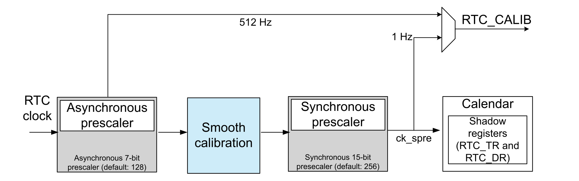
For RTC3 type, if LPCAL = 0 in RTC_CALR, ck_cal = RTCCLK. If LPCAL = 1, ck_cal = ck_apre (clock output by the RTC asynchronous prescaler). Moreover, when setting LPCAL to 1 and choosing ck_apre, the calibration consumption decreases, its accuracy remains the same and the calibration window changes to about 220 x PREDIV_A x RTCCLK pulses (instead of 220 RTCCLK pulses when LPCAL = 0).
The RTC clock can be calibrated with a resolution of about 0.954 ppm with a range from -487.1 ppm to +488.5 ppm.
This smooth digital calibration is designed to compensate the inaccuracy of crystal oscillators (due to temperature or crystal aging).
Figure 9. Smooth calibration block for RTC2 typeFigure 10. Smooth calibration block for RTC3 type (LPCAL = 1)
A smooth calibration consists of masking and adding N (configurable) 32 kHz-frequency pulses that are well distributed in a configurable window (8 s, 16 s or 32 s).
The number of masked or added pulses is defined using CALP and CALM[8:0] in RTC_CALR register.
By default, when the input frequency is 32768 Hz, the calibration window duration is 32 seconds (considering LPCAL = 0 for RTC3). It can be reduced to 8 or 16 seconds by setting CALW8 or CALW16 in RTC_CALR.
Note:
The 0.954 ppm accuracy of the smooth calibration is only achievable by 32 s calibration window, for 16 s, the best accuracy is (0.954 x 2), and for 8 s is (0.954 x 4).
Example 1
Setting CALM[0] = 1, CALP = 0 and using 32 s calibration window, results in exactly one pulse being masked for 32 s.
Example 2
Setting CALM[2] = 1, CALP = 0 and using 32 s calibration window, results in exactly four pulses being masked for 32 s.
Note: Both CALM[8:0] and CALP can be used. In this case, an offset ranging from -511 to +512 pulses can be added for 32 s (calibration window).
When the asynchronous prescaler is less than 3, CALP cannot be set to 1.
The formula to calculate the effective calibrated frequency (FCAL), given the input frequency FRTCCLK, is:
FCAL = FRTCCLK x [1 + (CALP x 512 - CALM) / (220 + CALM - CALP x 512)]
A smooth calibration can be performed on-the-fly, changed when the temperature changes or if other factors are detected.
Check the smooth calibration
The smooth calibration effect on the calendar clock (RTC clock) can be checked by calibration using one of the following:
RTC_CALIB output (1 Hz)
Subsecond alarms
Wake-up timer
Synchronize the RTC
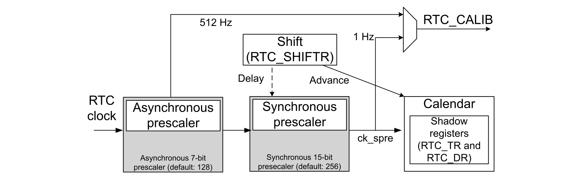
The RTC calendar can be synchronized to a more precise clock, “remote clock”, using the RTC shift feature. After reading the RTC subsecond field, a calculation of the precise offset between the time being maintained by the remote clock and the RTC is made. The RTC can be adjusted by removing this offset with a fine adjustment using the shift register control.Figure 11. RTC shift register
The synchronization shift function cannot be checked using the RTC_CALIB output since the shift operation has no impact on the RTC clock (except adding or subtracting a few fractions from the calendar counter).
Correct the RTC calendar time
If the RTC clock is advanced compared to the remote clock by n fractions of seconds, the offset value must be written in SUBFS[14:0] in RTC_SHIFTR, that is added to the synchronous prescaler counter. As this counter counts down, this operation effectively subtracts from (delays) the clock by:
Delay (seconds) = SUBFS / (PREDIV_S + 1)
If the RTC is delayed compared to the remote clock by n fractions of seconds, the offset value can effectively be added to the clock (advancing the clock) when ADD1S in RTC_SHIFTR is used in conjunction with SUBFS, effectively advancing the clock by:
For RTC3 type, ADD1S has no effect in binary mode. In mixed mode, the SUBFS[14:BCDU+8] must be written with 0. Before initiating a shift operation in BCD mode, the user must check that SS[15] = 0 in order to ensure that no overflow occurs. In mixed mode, the user must check that the bit SS[BCDU+8] = 0.
For RTC3 type, this feature is available only in BCD mode (BIN = 00).
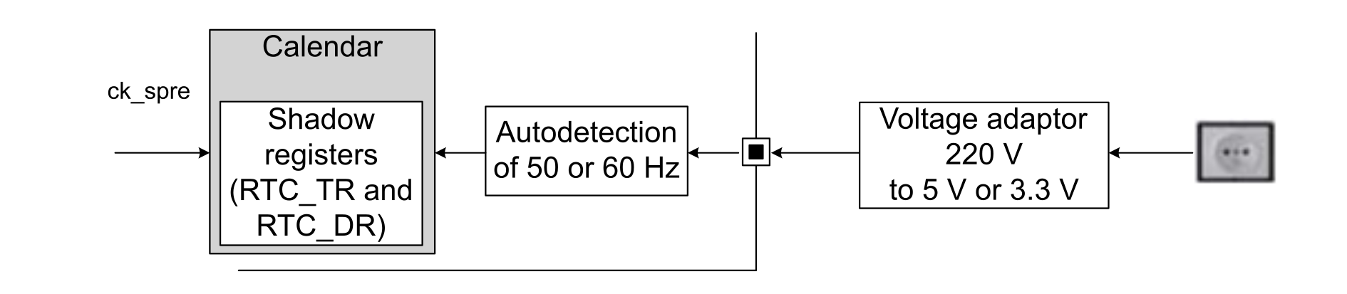
The reference clock (50 Hz or 60 Hz) must have a higher precision than the 32.768 kHz LSE clock. This is why the RTC provides a reference clock input (RTC_REFIN pin) that can be used to compensate the imprecision of the calendar frequency (1 Hz). The RTC_REFIN pin must be configured in input floating mode.
This mechanism enables the calendar to be as precise as the reference clock.
The reference clock detection is enabled by setting REFCKON in RTC_CR. When the reference clock detection is enabled, PREDIV_A and PREDIV_S must be set to their default values (PREDIV_A = 0x007F and PREDIV_S = 0x00FF).
Note:
This feature is only valid with the RTC clock from LSE oscillator oscillating at 32.768 kHz due to this requirement.
When the reference clock detection is enabled, each 1 Hz clock edge is compared to the nearest reference clock edge (if one is found within a given time window). In most cases, the two clock edges are properly aligned. When the 1 Hz clock becomes misaligned due to the imprecision of the LSE clock, the RTC shifts the 1 Hz clock a bit so that future 1 Hz clock edges are aligned. The update window is three ck_apre periods.
If the reference clock halts, the calendar is updated continuously based only on the LSE clock. The RTC waits for the reference clock using a detection window centered on the ck_spre (synchronous prescaler output clock) edge. The detection window is seven ck_apre periods.
The reference clock can have a large local deviation (for instance in the range of 500 ppm), but in the long term it must be much more precise than 32 kHz quartz.
The detection system is used only when the reference clock needs to be detected back after a loss. As the detection window is a bit larger than the reference clock period, this detection system brings an uncertainty of one ck_ref period (20 ms for a 50 Hz reference clock) because it is possible to have two ck_ref edges in the detection window. The update window is then used, which brings no error as it is smaller than the reference clock period.
Assuming that ck_ref is not lost more than once a day, the total uncertainty per month is 20 ms x 1x 30 = 0.6 s, which is much less than the uncertainty of a typical quartz (53 s/month for ±20 ppm quartz).
Figure 12. RTC reference clock detection
Note:
The reference clock calibration and the RTC synchronization (shift feature) cannot be used together. The reference clock calibration is the best (ensures a high calibrated time) if the 50 Hz is always available. If the 50 Hz input is lost, the RTC accuracy is provided by the LSE crystal. The reference clock detection cannot be used in VBAT mode. The reference clock calibration can only be used if the user provides a precise 50 or 60 Hz input.
When the LSI is selected as RTC clock source, a timer can be used to measure its frequency and adjust the RTC synchronous prescaler depending on the result got. The goal is to improve the observed LSI accuracy.
The LSI clock signal is connected to the input capture of one of the STM32 timers (see the timers connected to LSI in the product reference manual). For each LSI period, the timer must count the number of system core clock periods elapsed between two LSI rising edges associated. The software exploits the number of periods counted by comparing it with the amount expected, and adjust the RTC synchronous prescaler value in order to improve the RTC accuracy.
A firmware example is available in the STM32CubeL4 MCU Package for NUCLEO-L412RB-P (RTC3 type): STM32Cube_FW_L4_Vx.y.z\Projects\NUCLEO-L412RB-P\Examples\RTC\RTC_LSI
If one example is not available in the STM32Cube for a given STM32 MCU, the user can adapt it.