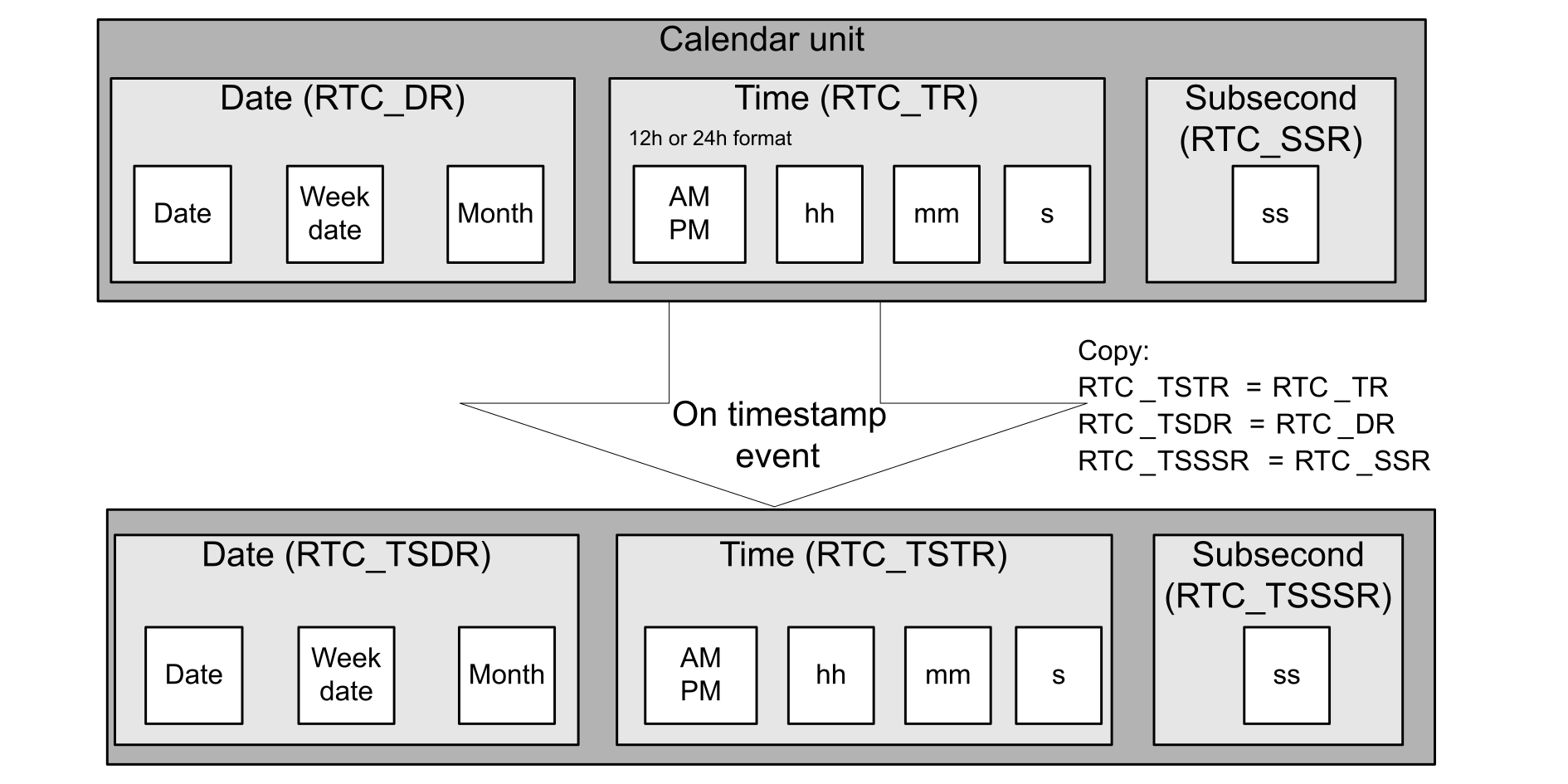
The timestamp feature is used to automatically save the current calendar when some specific events occur.Figure 13. Timestamp event procedure
When this function is enabled, the calendar is saved in the timestamp registers (RTC_TSTR, RTC_TSDR, RTC_TSSSR) when an internal or external timestamp event is detected. When a timestamp event occurs, the timestamp flag bit (TSF) is set in RTC_ISR (RTC2)/RTC_SR (RTC3).
The following events can generate a timestamp:
Edge detection on the RTC_TS I/O
Tamper event detection (from all RTC_TAMP I/Os)
Switch to VBAT when the main supply if powered off (available for example on STM32L4 series, see the product reference manual and datasheet to verify availability for other products)
Table 14. Timestamp features
What
How
Comments
Enable timestamp.
Set to 1 TSE, ITSE or TAMPTS in RTC_CR.
TAMPTS is only available on RTC3 to allow tamper events to trigger timestamp.
Detect a timestamp event by interrupt.
Set TSIE in RTC_CR.
An interrupt is generated when a timestamp event occurs.
Detect a timestamp event by polling.
Poll on the timestamp flags (TSF or ITSF1) in RTC_ISR (RC2)/RTC_SR (RTC3).
RTC_TSTR, RTC_TSDR, and RTC_TSSSR maintain the results of the previous event.
If a timestamp event occurs immediately after TSF is supposed to be cleared, then both TSF and TSOVF are set.
1 TSF is set two ck_apre cycles after the timestamp event occurs, due to the synchronization process.
2 To avoid masking a timestamp event occurring at the same moment, the application must not write 0 into TSF unless the software already read this bit at 1.
3 The timestamp overflow event is not connected to an interrupt.
4 There is no delay in TSOVF setting: if two timestamp events are close to each other, TSOVF can be seen as 1 while TSF is still 0. It is then recommended to poll TSOVF only after TSF has been set.
Timestamp firmware examples
The RTC comes with a set of example projects so that the user can quickly become familiar with this peripheral. Refer to the STM32Cube MCU Package of the product for a complete projects list.
For example, the user can find the following projects concerning timestamp:
If an example is not available in the STM32Cube for a given STM32 MCU, the user can adapt it.
RTC tamper detection function
The RTC includes several tamper detection inputs. The tamper inputs can be configured to detect different types of tamper events. Each tamper input has an individual flag (TAMPxF in RTC_ISR (RTC2)/TAMP_SR (RTC3)).
A tamper detection event generates an interrupt when TAMPIE or TAMPxIE is set in RTC_TAMPCR (RTC2)/TAMP_IER (RTC3).
The configuration of the tamper filter, TAMPFLT[1:0] in TAMP_FLTCR, defines whether the tamper detection is activated on edge (set TAMPFLT[1:0] = 00), or on level (TAMPFLT[1:0] ≠ 00).
The number of tamper inputs depends on product packages. Each input has a TAMPxF individual flag in RTC_ISR (RTC2)/TAMP_SR (RTC3).
The DBP bit (the register associated depends on the product), must be set to allow write access to any TAMP registers after a system reset.
Edge detection on tamper input
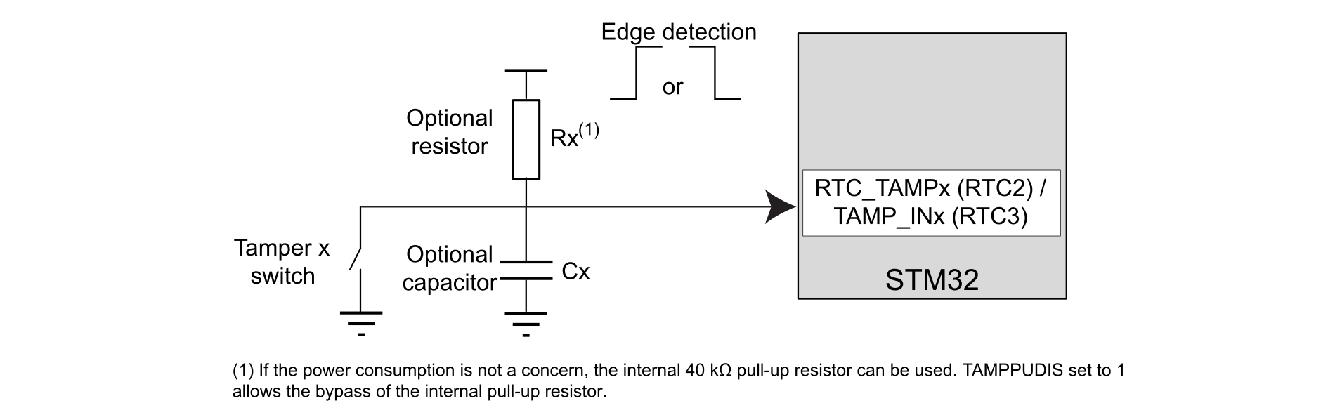
When TAMPFLT[1:0] = 00, the tamper input detection triggers when a rising edge or a falling edge (depending on TAMPxTRG) is observed on the input pin RTC_TAMPx (RTC2)/TAMP_INx (RTC3).Figure 14. Tamper with edge detection
Note:
With the edge detection, the sampling and precharge features are deactivated.
Table 15. Tamper features (edge detection)
What
How
Comment
Enable tamper.
Set TAMPxE = 1 in RTC_TAMPCR (RTC2)/TAMP_CR1 (RTC3).
-
Select tamper active edge detection.
Select with TAMPxTRG in RTC_TAMPCR (RTC2)/TAMP_CR2 (RTC3).
The default edge is rising edge.
Detect a tamper event by interrupt.
Set TAMPIE or TAMPxIE in RTC_TAMPCR (RTC2)/TAMP_IER (RTC3) register
An interrupt is generated when a tamper detection event occurs.
Detect a tamper event by polling.
Poll TAMPxF in the RTC_ISR (RTC2)/TAMP_SR (RTC3).
RTC2: To clear the flag, write zero in TAMPxF.
RTC3: Write 1 in CTAMPxF in TAMP_SCR clears TAMPxF in TAMP_SR.
Level detection on tamper input
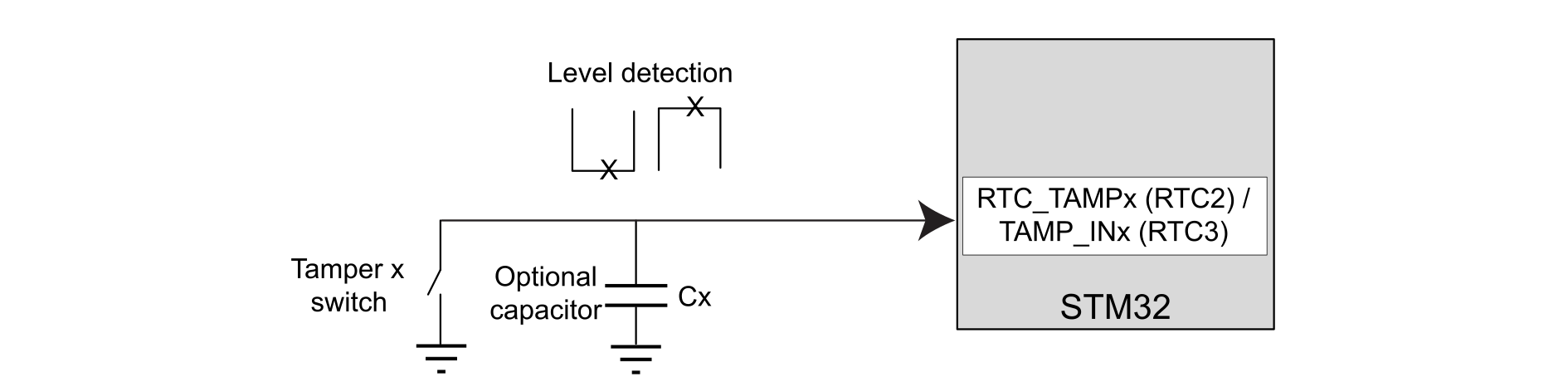
Setting TAMPFLT[1:0] to a value other than zero means that the tamper input triggers when a selected level (high or low) is observed on the corresponding input pin RTC_TAMPx (RTC2)/TAMP_INx (RTC3).
A tamper detection event is generated when either two, four or eight (depending on the TAMPFLT value) consecutive samples are observed at the selected level.
Figure 15. Tamper with level detection
Using the level detection (TAMPFLT[1:0] ≠ 0), the tamper input pin can be precharged by resetting TAMPPUDIS through an internal resistance before sampling its state. In order to support the different capacitance values, the length of the pulse during which the internal pull-up is applied can be one, two, four or eight RTCCLK cycles (see TAMPPRCH[1:0]).
Figure 16. Tamper sampling with precharge pulse
Note:
When the internal pull-up is not applied, the I/O Schmitt triggers are disabled in order to avoid an extra consumption if the tamper switch is open.
The trade-off between the tamper detection latency and the power consumption through the weak pull-up or external pull-down can be reduced by using a tamper sampling frequency feature. The tamper sampling frequency is determined by configuring TAMPFREQ[2:0] in RTC_TAMPCR (RTC2)/TAMP_FLTCR (RTC3) register. When using the LSE at 32768 Hz as the RTC clock source, the sampling frequency can be 1, 2, 4, 8, 16, 32, 64, or 128 Hz.
Table 16. Tamper features (level detection)
What
How
Comment
Enable tamper.
Set to 1 TAMPxE in RTC_TAMPCR (RTC2)/TAMP_CR1 (RTC3).
-
Configure tamper filter count.
Configure TAMPFLT bits in RTC_TAMPCR (RTC2)/TAMP_FLTCR (RTC3).
-
Configure tamper sampling frequency .
Configure TAMPFREQ bits in RTC_TAMPCR (RTC2)/TAMP_FLTCR (RTC3).
Default value is 1Hz.
Configure tamper internal pull-up and precharge duration.
Configure TAMPPUDIS and TAMPPPRCH in RTC_TAMPCR (RTC2)/TAMP_FLTCR (RTC3).
-
Select tamper active edge/level detection.
Select with RTC_TAMPCR (RTC2)/TAMP_CR2 (RTC3).
Edge or level depends on tamper filter configuration.
Detect a tamper event by interrupt.
Set TAMPIE or TAMPxIE in RTC_TAMPCR (RTC2)/TAMP_IER (RTC3).
An interrupt is generated when tamper detection event occurs.
Detect a tamper event by polling.
Poll TAMPxF in RTC_ISR (RTC2)/TAMP_SR (RTC3).
To clear the flag, write zero in TAMPxF.
Action on tamper detection event
By setting TAMPTS = 1, any tamper event (with edge or level detection) causes a timestamp to occur. The timestamp and timestamp overflow flags are then set when the tamper flag is set and work in the same manner as when a normal timestamp event occurs.
Note:
It is not necessary to enable or disable the timestamp function when using this feature.
Other actions than a timestamp can be triggered by a tamper detection depending on the product used. Refer to the product documentation for a complete list of actions.
For example, a tamper detection can:
Erase the backup registers, SRAMs content or specific peripheral registers
Generate an interrupt that can wake up the device from low-power modes
Generate an hardware trigger for a low-power timer or a RTC timestamp event (see TAMPTS bit mentioned before)
On some product, the protection of specific device assets can be enabled/disabled thanks to the ERCFGy bit in TAMP_ERCFGR. If this bit is set, in case of a tamper detection or when BKBLOCK = 1 in TAMP_CR2, the read/write accesses to the concerned device assets are blocked.
Active tamper detection (RTC3 only)
The tamper detection can be made robust against tamper pin being externally opened or shorted. That is done thanks to the active tamper.
The principle is to set TAMP_OUTy output pins to deliver a random message, and TAMP_INx input pins to receive it. If the message sent is not the one received, it is considered that a tamper event occurred: TAMPxF is set in TAMP_SR for the TAMP_INx pin detecting the error. Depending on the tamper pins available, several organizations can be configured. For example, for eight tamper pins, the user can have four outputs and four inputs with four different messages, or seven inputs with one output and one message exchanged.
Figure 17. Tamper detection
Active pin IN/OUT association
The user configures TAMP_INx as active input pins by setting TAMPxAM = 1 in TAMP_ATCR1.
By default, when TAMP_INx is activated as active tamper pins, the TAMP_OUTx pin is associated to it to implement the active tamper detection mechanism.
If other TAMP_INy pins need to be associated to TAMP_OUTx pin (the one mentioned above) for the application, the ATOSHARE (active tamper output share) bit can be used to make all the TAMP_OUT pins, including TAMP_OUTx, sharable.
When ATOSHARE = 1, ATOSELi (active tamper output selection) allows the choice of the new TAMP_OUT pin associated to TAMP_INi.
Example: considering there are at least two active tamper pins on the product, TAMP_OUT1 can be used for comparison with TAMP_IN1 and TAMP_IN2 by configuring and enabling both TAMP_IN1 and TAMP_2 in active mode, with ATOSHARE = 1, ATOSEL1 = 0 and ATOSEL2 = 0.
Note:
ATOSHARE and ATOSELi bits are respectively in TAMP_ATCR1 and TAMP_ATCR2.
Filtering
As for passive tamper detections (not active ones), the input can be filtered by setting FLTEN = 1. With this action, a tamper event is triggered when two comparisons among four are false (received message different from the sent one).
Message randomization
Concerning the randomization of the message sent by the active output pins, a pseudo-random number generator (PRNG value in TAMP_ATOR) is used and need to be fed periodically with a new seed. To ensure that, the user needs to maintain four 32-bit random values in the code. These last one are not necessarily generated by a random generator, the user can choose random values and update it with a mathematical formula.
By writing consecutively these four values in TAMP_ATSEEDR register, the user feeds the PRNG and allows active output pins to renew the randomization of their message.
The PRNG takes several APB clock cycles (refer to the product documentation) to take into account the seed given, during this time the SEEDF bit in the TAMP_ATOR register is set and the TAMP_APB clock must not be switched off. Active tamper output pins are only activated after the PRNG has taken its seed into account. Then, the user must wait SEEDF to be cleared before, for example, entering low-power modes.
If the user does not want to enter low-power modes, the update of the seed can be done during tamper active activity. The update rate for the seeds depends on the number of tamper active outputs used, the product reference manual gives advisable time references for this action.
Initialization
If INITS is not set in TAMP_ATOR register, the active tamper initialization must be done:
Configure the active tamper clock prescaler with ATCKSEL in TAMP_ATCR1. Set the filter and associate TAMP in and out pins as needed (explained above).
Enable tamper pins used in TAMP_CR1 register (all in the same write access).
Feed the PRNG and wait for SEEDF to be cleared. Then backup registers are protected by active tamper.
If INITS is set, the tamper active feature is already initialized. The user only must update the PRNG seed for a more robust randomization.
Internal tamper detection (RTC3 only)
The internal tamper detection feature allows the detection of transient and environmental perturbations. An internal tamper event is enabled with ITAMPxE in TAMP_CR1. The interrupt is enabled by setting ITAMPxIE in TAMP_IER. Then, if the event occurs, ITAMPxF is set in TAMP_SR, and ITAMPxMF is set in TAMP_MISR if the interrupt has been enabled.
To clear both flags (polling and interrupt mode), the corresponding bit in TAMP_SCR must be set.
The STM32 MCUs implement some of the internal tampers listed below (refer to product reference manual):
ITAMP1: supply voltage monitoring (or backup domain voltage monitor)
ITAMP2: temperature monitoring
ITAMP3: LSE monitoring (CSS)
ITAMP4: HSE monitoring (CSS)
ITAMP5: RTC calendar overflow
ITAMP6: JTAG/SWD access when RDP > 0 (or NVSTATE != open in STM32H5)
ITAMP7: ADC analog watchdog monitoring 1
ITAMP8: monotonic counter 1 overflow
ITAMP9: cryptographic peripheral fault (SAES, AES, PKA or RNG)
ITAMP10: reserved
ITAMP11: IDWG reset when tamper flag is set (potential tamper timeout)
ITAMP12: ADC analog watchdog monitoring 2
ITAMP13: ADC analog watchdog monitoring 3
ITAMP14: reserved
ITAMP15: system fault
ITAMP16: reserved
Moreover, the electrical characteristics for each event depend on the device. Refer to the datasheet to get precise values and conditions on event triggering (example: voltage value threshold for voltage monitoring).
As for every tamper detection features, the internal tamper events allow attacks to be detected on the MCU. For instance, some attacks consist in going back in time in the RTC calendar to execute specific code. Since the user can only increment the RTC physically, going back in time can be done by making it overflow. This justifies the existence of the ITAMP5 signal.
The RTC3 tamper detection unit embeds also a monotonic counter implemented in TAMP_COUNTR register (called TAMP_COUNT1R on some products) and associated to ITAMP8. See Table 4 Advanced features for RTC2 type and AN4759_Adv-RTC-features.html#id_33173__table_hqc_shf_rpb for the availability in the product. This register can be read and is incremented each time the user writes it whatever the written value. TAMP_COUNTR cannot roll-over and is frozen when reaching its maximum. This register can be used in the application as a low-power counter robust to system reset. For example, it can count the number of time a sensitive part of code is executed to verify it does not exceed a limit. In that case, ITAMP8 can be used to trigger a tamper event.
ITAMP7, ITAMP12 and ITAMP13 are associated to analog watchdogs and are used to consider that an ADC channel going out of a configured voltage range is a tamper event (see the documentation of the products featuring this internal tamper for more details).
Potential detection management (RTC3 only)
If TAMPxNOER = 0 in TAMP_CR2 or ITAMPxNOER = 0 in TAMP_CR3, the backup registers and other device secrets are automatically erased by hardware on an external (passive or active) or internal tamper event.
In order to perform software filtering of the tamper event, the user must configure these bits to 1. In this case, the backup registers and device secrets are not erased but their read/write access is blocked as long as at least one of the tamper flag is set (TAMPxF and ITAMPxF). These tamper events are considered as potential tampers, and the user can investigate if the tamper event corresponds to a true or to a false tamper, and then take the necessary actions.
If the user confirms it is a true tamper detection, backup registers and device secrets can be erased by setting BKERASE = 1 in TAMP_CR2. If the tamper is not confirmed and is considered a false detection, the user must clear the tamper status flag. When all tamper flags are cleared, the access to backup registers and device secrets is possible again.
By associating the NOERASE feature with the IWDG (independent watchdog), a timeout can be implemented to automatically launch hardware erasing after a potential tamper detection. On some products, the ITAMP11 is associated to the IWDG reset. In this case, if a tamper event in NOERASE configuration is detected, and if a IWDG reset occurs before the software has cleared the tamper flag, the backup registers and device secrets are automatically erased by hardware. The probability that a software issue, preventing from refreshing the watchdog, occurs at the same time than a tamper detection is very low so the hardware considers it is a real attack.
Tamper detection firmware examples
The RTC comes with a set of example projects so that the user can quickly become familiar with this peripheral. Refer to the STM32Cube MCU Package of the product for a complete projects list.
For example, the user can find the following projects concerning tamper detection:
For most microcontrollers equipped with either an RTC2 or an RTC3: