Reduce power consumption
The RTC is designed to minimize the power consumption and can be configured to optimize further its consumption.
The RTC is designed to minimize the power consumption and can be configured to optimize further its consumption.
The precise list of modes compatible with the product and their consumption are listed in product reference manual and datasheet.
Thanks to the RTC wakeup unit, the user can wake up the STM32 MCU from this mode. Depending on the application needs in term of low-power phases and current consumption target, the adequate low-power mode and wakeup frequency must be selected.
The internal pull-up resistor in the tamper input pad is only applied for a short period of time (1, 2, 4 or 8 RTCCLK cycles). Using this RTC internal pull-up resistor instead of standard I/O pull-up/pull-down or external pull-up/pull-down ensures a lowest power consumption.
The trade-off between the tamper detection latency and the power consumption by the RTC internal pull-up can be optimized using TAMPFREQ[2:0], that determines the frequency of the tamper sampling from 128 Hz to 1 Hz when RTCCLK equals 32768 Hz.
Refer to the product datasheet/reference manual for the availability/electrical characteristics of the pull‑up resistors.
The prescalers used for the calendar are divided into an asynchronous and a synchronous prescalers. Increasing the PREDIV_A value of the asynchronous prescaler while reducing the synchronous prescaler accordingly to keep the 1 Hz output, reduces the RTC power consumption.
On RTC3 type, the RTC dynamic consumption is optimized for LPCAL = 1 and PREDIV_A + 1 being a power of two (considering the RTC as the only peripheral using LSE).
The prescaler linked to the LSI clock can also optimize the consumption. The user needs to select the LSI as RTC clock source. This prescaler divides LSI by 128 to get a rough 250 Hz clock instead of the former 32 kHz. This is activated by LSIPRE in RCC_CSR.
Concerning the LSE, users can select a crystal that allows setting the driving strength to the lowest level. The driving strength is determined by the chosen crystal parameters, such as load capacitance, ESR, and shunt capacitance, which define a critical transconductance (gmcrit). For more information, see AN2867.
Reducing the driving strength to the lowest level can lower consumption to a typical 250 nA, compared to 630 nA for high drive capability.
Set LSEDRV to 00 in RCC_BDCR to select the lowest driving strength.
The RTC comes with a set of example projects so that the user can quickly become familiar with this peripheral. Refer to the STM32Cube MCU Package of the product for a complete projects list.
STM32Cube_FW_L4_Vx.y.z\Projects\NUCLEO-L412RB-P\Examples\RTC\RTC_LowPower_STANDBY
STM32Cube_FW_L4_Vx.y.z\Projects\NUCLEO-L412KB\Examples\PWR\PWR_STANDBY_RTC
STM32Cube_FW_L4_Vx.y.z\Projects\NUCLEO-L412KB\Examples\PWR\PWR_STOP1_RTC
STM32Cube_FW_L4_Vx.y.z\Projects\NUCLEO-L412KB\Examples\PWR\PWR_STOP2_RTC
Analogous examples are available for STM32F0, STM32F2, STM32F3, STM32F4, STM32F7, STM32G4, STM32H7, STM32L0, STM32L1, STM32U3, STM32U5, STM32WB and STM32WL. If one example is not available in the STM32Cube for a given STM32 MCU, the user can adapt it.
Some STM32 MCUs can run in secure or nonsecure mode. Each mode having its own environment, allowing a trustful zone, not accessible in nonsecure mode, to be maintained in secure mode (TrustZone® feature).
A second level of restriction and security is available with part of each environment associated to a privileged or unprivileged mode.
On some products (see Table 4 Advanced features for RTC2 type and AN4759_Adv-RTC-features.html#id_33173__table_hqc_shf_rpb), the registers programming allow the user to restrict the read/write operation on RTC/TAMP registers to secure or privileged modes. Some configuration bits establish the restriction only for some RTC registers. These registers/bits to program are product dependent, then not detailed here (refer to the product reference manual).
The backup registers and the monotonic counter have their own protection mode settings.
Refer to stm32l4xx_hal_rtc.c and stm32l4xx_hal_rtc_ex.c files in \STM32Cube_FW_L4_Vx.y.z\Drivers\STM32L4xx_HAL_Driver\
X-CUBE-RTC shows an example where a real-time clock must be maintained alive while using as low power as possible (STM32CubeExpansion_AN4759_RTC_STM32L_Vx.y.z\Projects\STM32L476G_EVAL\RTC_TamperVBATT).
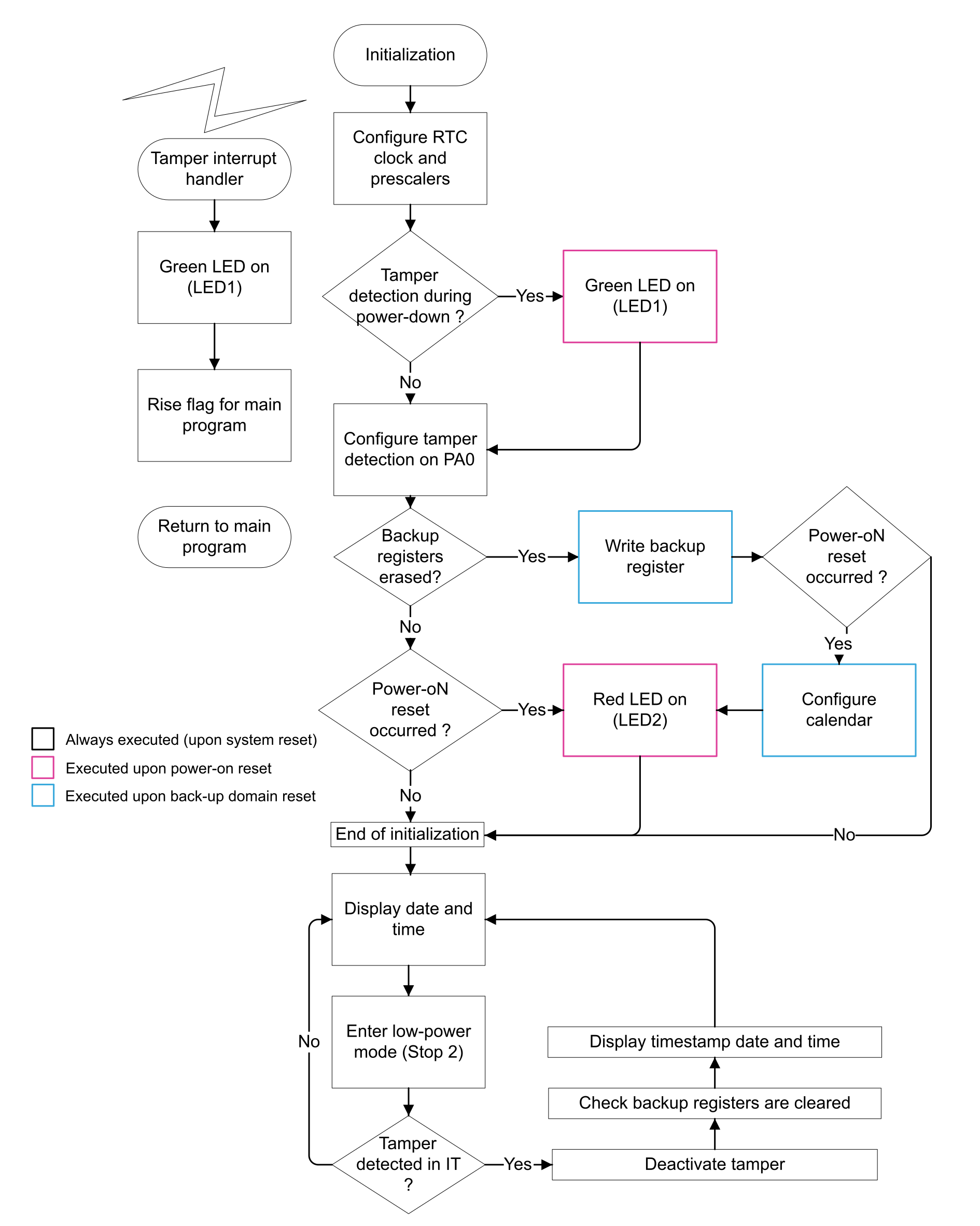

PC13 (tamper pin 1) connected to the blue push-button is not used in this demonstration firmware as it is connected to an external pull-down resistor preventing the use of the tamper detection on level with internal pull-up (the lowest consumption mode).
For more information, refer to the user manual Evaluation board with STM32L476ZGT6 MCU (UM1855).
Open the project under the user favorite IDE (integrated development environment). For IAR Embedded Workbench®, open the project.eww file. For Keil® MDK-‑ARM, open the project.uvprojx file, compile and launch the debug session. For SW4STM32, open the SW4STM32 toolchain, browse to the SW4STM32 workspace directory, select and import the project RTC_TamperVBATT. Launching the debug session loads the program in the internal Flash memory and executes it.
The same observation can be done using MDK-ARM development tools. To open the Watch1 window, do View\Watch Windows\Watch1.
TFT displays: the tamper date and tamper time are different from their initialization state.
TFT displays: the tamper date and tamper time are at their initialization state.
TFT displays: “error occurred” is displayed.
TFT displays: the tamper date and tamper time are at their initialization state.
Disconnect the debugger. A power-on reset can be generated by removing the JP17 jumper and placing it again on ST‑LINK.
A long delay (up to 2 seconds) may be observed before the tamper event is detected. This is due to the trade-off in the tamper detection frequency (TAMPFREQ) chosen to ensure the lowest power consumption.
A reset can be applied by pushing the black reset button. The application is now able the detect a new tamper event.
If the user supplies the VBAT pin with 3 V (JP12 on VDD position), the RTC is no longer supplied when the main power supply is switched off. The application is no longer able to detect the tampering event while the main power supply is off.