RTC alarm configuration
The RTC embeds two equivalent alarms: alarm A and alarm B. An alarm can be generated at a given time or/and date programmed by the user. The RTC provides a rich combination of alarm settings, and offers many features to make them easy to configure and display.
Each alarm unit provides the following features:
- Fully programmable alarm: subsecond, second, minute, hour and date fields can be independently selected or masked to provide a rich combination of alarms.
- The device can be wake up from low-power modes when the alarm occurs.
- The alarm event can be routed to a specific output pin with configurable polarity.
- Dedicated alarm flags and interrupt are available.
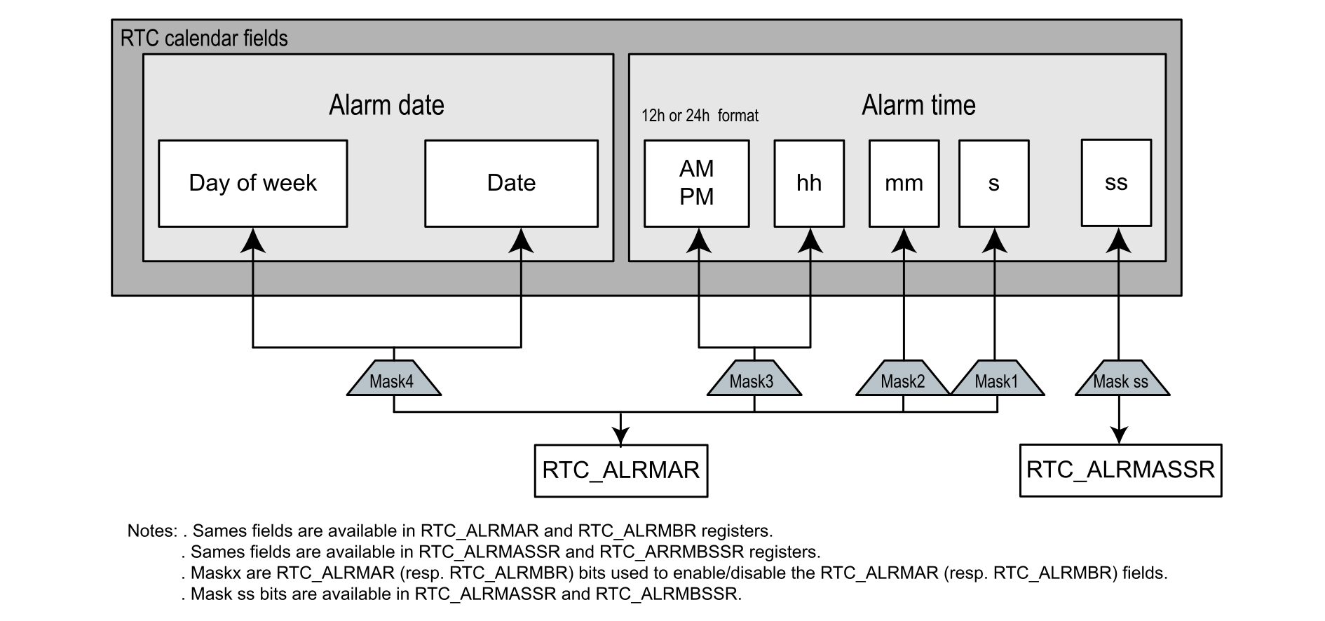
The time configuration bitfields of the alarm configuration register are mapped into the same bit offsets as those on the RTC_TR time register, for easier software manipulation. When the RTC time counter reaches the value programmed in the alarm register, a flag is set to indicate that an alarm event occurred (ALRAF‑or‑ALRBF‑in‑RTC_SR).
The RTC alarm can be configured by hardware to generate different types of alarms. For more details, refer to Table 9 Alarm combinations.
Program the alarm
The table below describes the steps required to configure alarm A.
| Step | What | How | Comment |
|---|---|---|---|
| 1 | Disable write protection on RTC registers. | Write 0xCA and then 0x53 into RTC_WPR. | The RTC registers can be modified. |
| 2 | Disable alarm A. | Clear ALRAE1 in RTC_CR2. | - |
| 33 | Check that RTC_ALRMAR can be accessed. | Poll ALRAWF4 until it is set in RTC_ISR. | It takes around two RTCCLK clock cycles due to clock synchronization. |
| 4 | Configure the alarm. | Configure RTC_ALRMAR5. | The alarm hour format must be the same6 as the RTC calendar in RTC_ALRMAR5. |
| 5 | Re-enable alarm A. | Set ALRAE7 in RTC_CR. | - |
| 6 | Enable write protection on the RTC registers. | Write 0xFF into RTC_WPR. | The RTC registers can no longer be modified. |
1 Respectively ALRBE for alarm B.
2 RTC alarm registers can only be written when the corresponding RTC alarm is disabled, or during RTC initialization mode.
3 Only required for RTC2 type.
4 Resp. ALRBWF for alarm B. ALRAWF and ALRBWF does not exist on RTC3 type.
5 Respectively RTC_ALRMBR for alarm B.
6 As an example, if the alarm is configured to occur at 3:00:00 PM, the alarm does not occur even if the calendar time is 15:00:00, because the RTC calendar is 24-hour format and the alarm is 12-hour format.
7 Respectively ALRBE for alarm B.
Configure the alarm behavior using the MSKx bits
The alarm behavior can be configured using the MSKx bits (x = 1, 2, 3, 4) of RTC_ALRMAR for alarm A (RTC_ALRMBR for alarm B). The table below shows all possible alarm settings.
| MSK4 | MSK3 | MSK2 | MSK1 | Alarm behavior |
|---|---|---|---|---|
| 0 | 0 | 0 | 0 | All fields are used in the alarm comparison. Example: the alarm occurs at 23:15:07, each Monday. |
| 0 | 0 | 0 | 1 | Seconds do not matter in the alarm comparison. Example: the alarm occurs every second of 23:15, each Monday. |
| 0 | 0 | 1 | 0 | Minutes do not matter in the alarm comparison. Example: the alarm occurs at the 7th second of every minute of 23:XX, each Monday. |
| 0 | 0 | 1 | 1 | Minutes and seconds do not matter in the alarm comparison. |
| 0 | 1 | 0 | 0 | Hours do not matter in the alarm comparison. |
| 0 | 1 | 0 | 1 | Hours and seconds do not matter in the alarm comparison. |
| 0 | 1 | 1 | 0 | Hours and minutes do not matter in the alarm comparison. |
| 0 | 1 | 1 | 1 | Hours, minutes and seconds do not matter in the alarm comparison. Example: the alarm is set every second, each Monday, during the whole day. |
| 1 | 0 | 0 | 0 | Week day (or date, if selected) do not matter in the alarm comparison. Example: the alarm occurs all the days at 23:15:07. |
| 1 | 0 | 0 | 1 | Week day and seconds do not matter in the alarm comparison. |
| 1 | 0 | 1 | 0 | Week day and minutes do not matter in the alarm comparison. |
| 1 | 0 | 1 | 1 | Week day, minutes and seconds do not matter in the alarm comparison. |
| 1 | 1 | 0 | 0 | Week day and hours do not matter in the alarm comparison. |
| 1 | 1 | 0 | 1 | Week day, hours and seconds do not matter in the alarm comparison. |
| 1 | 1 | 1 | 0 | Week day, hours and minutes do not matter in the alarm comparison. |
| 1 | 1 | 1 | 1 | The alarm occurs every second. |
Example
To configure the alarm time to 23:15:07 on Monday assuming WDSEL = 1, configure all MSKx to zero with DU[3:0] = 0001 (Monday), HT[1:0] = 10, HU[3:0] = 0011, MNT[2:0] = 001, MNU[3:0] = 0101, ST[2:0] = 000, SU[3:0] = 0111 (23:15:07), PM = 0 (24h format) in RTC_ALRMAR (resp. RTC_ALRMBR) .
When WDSEL = 0, an alarm occurs on the day number specified in DT and DU bitfields in RTC_ALRMxR, instead of the day of the week. To get this alarm once a month at 23:15:07, on the 14th day, RTC_ALRMxR bitfields must be set as follows: all MSKx = 0, WDSEL = 0, DT[1:0] = 01, DU[3:0] = 0100, HT[1:0] = 10, HU[3:0] = 0011, MNT[2:0] = 001, MNU[3:0] = 0101, ST[2:0] = 000, SU[3:0] = 0111, PM = 0.
CAUTION:
If the second field is selected (MSK1 reset in RTC_ALRMAR or RTC_ALRMBR), the synchronous prescaler division factor PREDIV_S[14:0] (set in RTC_PRER) must be at least 3 to ensure a correct behavior.
Alarm subsecond configuration
Only RTC3 type with BCD or mixed mode is considered in this section.
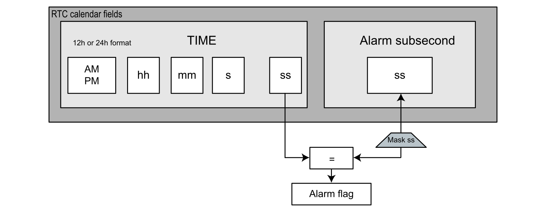
The RTC provides similar programmable alarms, subsecond A and B. They generate alarms with a high resolution (for the second division). The value programmed in the alarm subsecond register is compared to the content of the subsecond field in the calendar unit.
The subsecond field counter counts down from the value configured in the synchronous prescaler to zero, and then reloads a value from RTC_SPRE.
Note:
Mask ss is the most significant bit in the subsecond alarm. This bit is compared to the synchronous prescaler register. Mask ss is 4-bit length (from 0 to 15) for RTC2 type, and can be up to 6-bit length (from 0 to 31) for RTC3 type (RTC_SSR always 16-bit length for RTC2 type, and can be expanded to 32 bits on some RTC3 type).
The subsecond alarm is configured using MASKSS[5:0] in RTC_ALRMASSR (resp. RTC_ALRMBSSR). The table below shows the configuration possibilities for the mask register and provides an example with the following settings:
- LSE selected as RTC clock source (for example LSE = 32768 Hz)
- Asynchronous prescaler = 127
- Synchronous prescaler = 255 (calendar clock = 1 Hz)
- Alarm A subsecond = 255 (SS[14:0] = 255)
| MASKSS[5:0] | Alarm A subsecond behavior | Example result |
|---|---|---|
| 0 | No comparison on subsecond for alarm The alarm is activated when the second unit is incremented. | Alarm activated every 1 s |
| 1 | Only the AlarmA_SS[0] bit is compared to RTC_SSR. | Alarm activated every 1/128 s |
| 2 | Only the AlarmA_SS[1:0] bits are compared to RTC_SSR. | Alarm activated every 1/64 s |
| 3 | Only the AlarmA_SS[2:0] bits are compared to RTC_SSR. | Alarm activated every 1/32 s |
| 4 | Only the AlarmA_SS[3:0] bits are compared to RTC_SSR. | Alarm activated every 1/16 s |
| 5 | Only the AlarmA_SS[4:0] bits are compared to RTC_SSR. | Alarm activated every 125 ms |
| 6 | Only the AlarmA_SS[5:0] bits are compared to RTC_SSR. | Alarm activated every 250 ms |
| 7 | Only the AlarmA_SS[6:0] bits are compared to RTC_SSR. | Alarm activated every 500 ms |
| 8 | Only the AlarmA_SS[7:0] bits are compared to RTC_SSR. | Alarm activated every 1 s |
| 9 | Only the AlarmA_SS[8:0] bits are compared to RTC_SSR. | Alarm activated every 1 s |
| 10 | Only the AlarmA_SS[9:0] bits are compared to RTC_SSR. | Alarm activated every 1 s |
| 11 | Only the AlarmA_SS[10:0] bits are compared to RTC_SSR. | Alarm activated every 1 s |
| 12 | Only the AlarmA_SS[11:0] bits are compared to RTC_SSR. | Alarm activated every 1 s |
| 13 | Only the AlarmA_SS[12:0] bits are compared to RTC_SSR. | Alarm activated every 1 s |
| 14 | Only the AlarmA_SS[13:0] bits are compared to RTC_SSR. | Alarm activated every 1 s |
| 15 | Only the AlarmA_SS[14:0] bits are compared to RTC_SSR. | Alarm activated every 1 s |
Note: For RTC3 type, this table can be completed up to MASKSS equal to 31 and the SS[31:16] value is given by RTC_ALRABINR (resp. RTC_ALRBBINR).
The overflow bit in the subsecond register (bit 15 for RTC2 and 31 for RTC3) is never compared.
Alarm firmware examples
The RTC comes with a set of example projects so that the user can quickly become familiar with this peripheral. Refer to the X-CUBE-RTC Expansion Package for a complete projects list.
For example, the user can find the following projects concerning alarms:
- For the NUCLEO-L412RB-P equipped with an RTC3:
- STM32Cube_FW_L4_Vx.y.z\Projects\NUCLEO-L412RB-P\Examples\ RTC\RTC_Alarm
- STM32Cube_FW_L4_Vx.y.z\Projects\NUCLEO-L412RB-P\Examples_LL\RTC\RTC_Alarm
- STM32Cube_FW_L4_Vx.y.z\Projects\NUCLEO-L412RB-P\Examples_LL\RTC\RTC_Alarm_Init
If one example is not available in the X-CUBE-RTC for a given STM32 MCU, the user can adapt it.