DS14928 · DatasheetArm® Cortex®-M33 32-bit MCU with FPU, 144 MHz, 593 CoreMark®, up to 512‑Kbyte dual‑bank flash memory, 128-Kbyte RAM
Download .pdfOpen in the full document

Package information

Package information

To meet environmental requirements, ST offers these devices in different grades of ECOPACK packages, depending on their level of environmental compliance. ECOPACK specifications, grade definitions and product status are available at: www.st.com. ECOPACK is an ST trademark.

Device marking

Refer to technical note "Reference device marking schematics for STM32 microcontrollers and microprocessors" (TN1433) available on www.st.com, for the location of pin 1 / ball A1 as well as the location and orientation of the marking areas versus pin 1 / ball A1.

Parts marked as "ES", "E" or accompanied by an engineering sample notification letter, are not yet qualified and therefore not approved for use in production. ST is not responsible for any consequences resulting from such use. In no event will ST be liable for the customer using any of these engineering samples in production. ST’s Quality department must be contacted prior to any decision to use these engineering samples to run a qualification activity.

A WLCSP simplified marking example (if any) is provided in the corresponding package information subsection.
LQFP32 package information (5V)

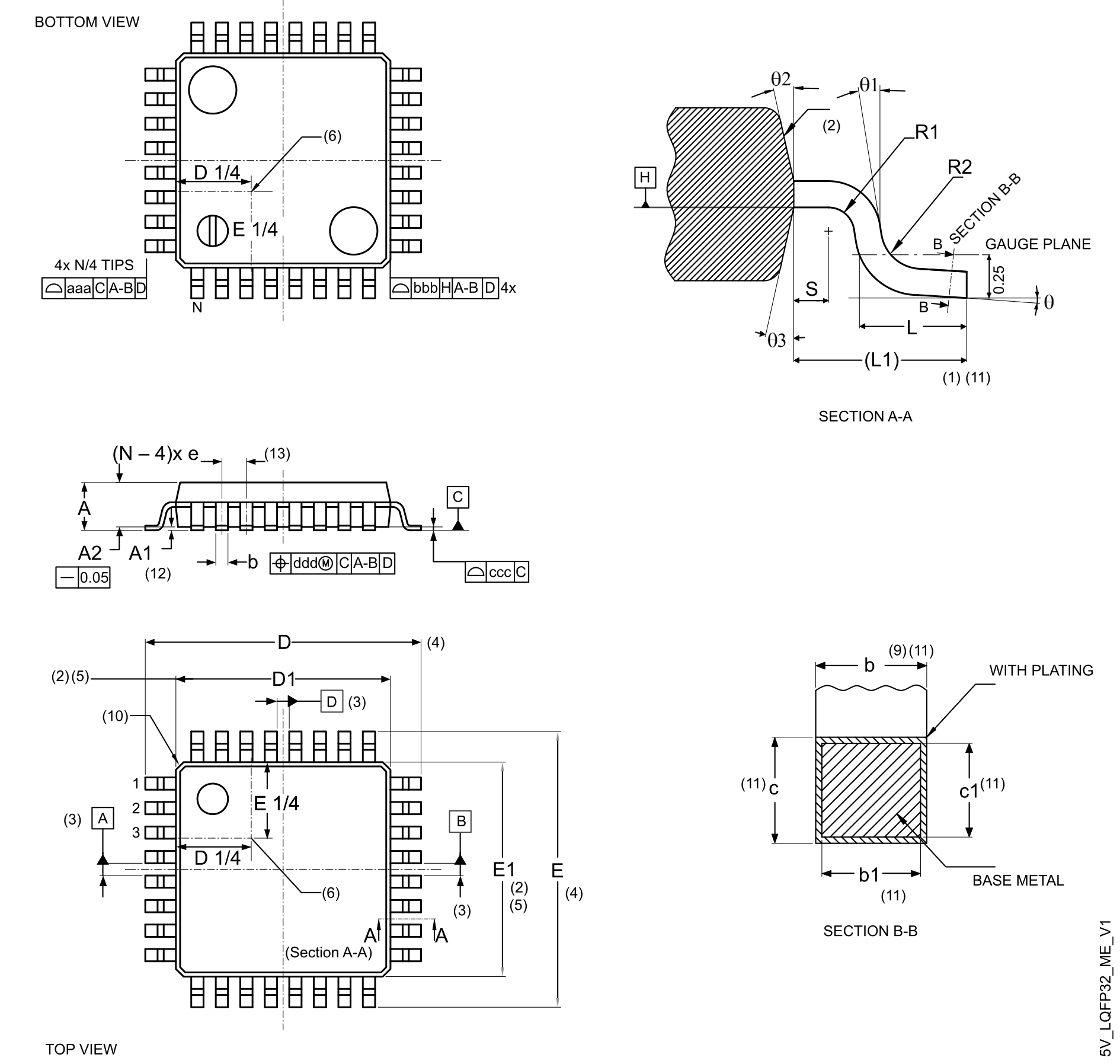
This LQFP is a 32-pin, 7 x 7 mm, low-profile quad flat package.
Note:

Figure 37 LQFP32- Outline is not to scale.

Refer to the notes section for the list of notes on Figure 37 LQFP32- Outline and Table 71 LQFP32 - Mechanical data.

Figure 37. LQFP32- Outline
Table 71. LQFP32 - Mechanical data
SymbolMillimetersInches(14)
MinTypMaxMinTypMax
θ0°3.5°7°0°3.5°7°
θ10°--0°--
θ210°12°14°10°12°14°
θ310°12°14°10°12°14°
A--1.60--0.0630
A1(12)0.05-0.150.0020-0.0059
A21.351.401.450.05310.05510.0571
b(9)(11)0.300.370.450.01180.01460.0177
b1(11)0.300.350.400.01180.01280.0157
c(11)0.09-0.200.0035-0.0079
c1(11)0.09-0.160.0035-0.0063
D(4)9.00 BSC0.3543 BSC
D1(2)(5)7.00 BSC0.2756 BSC
e0.80 BSC0.0315 BSC
E(4)9.00 BSC0.3543 BSC
E1(2)(5)7.00 BSC0.2756 BSC
L0.450.600.750.01770.02360.0295
L11.00 REF0.0394 REF
N(13)32
R10.08--0.0031--
R20.08-0.200.0031-0.0079
S0.20--0.0079--
aaa(1)(7)(15)0.200.0079
bbb(1)(7)(15)0.200.0079
ccc(1)(7)(15)0.100.0039
ddd(1)(7)(15)0.200.0079

Notes:

  1. Dimensioning and tolerancing schemes conform to ASME Y14.5M-1994.
  2. The top package body size may be smaller than the bottom package size by as much as 0.15 mm.
  3. Datums A-B and D to be determined at datum plane H.
  4. To be determined at the seating datum plane C.
  5. Dimensions D1 and E1 do not include mold flash or protrusions. Allowable mold flash or protrusions is “0.25 mm” per side. D1 and E1 are maximum plastic body size dimensions including mold mismatch.
  6. Details of pin 1 identifier are optional but must be located within the zone indicated.
  7. All dimensions are in millimeters.
  8. No intrusion is allowed inwards the leads.
  9. Dimension b does not include a dambar protrusion. Allowable dambar protrusion shall not cause the lead width to exceed the maximum “b” dimension by more than 0.08 mm. Dambar cannot be located on the lower radius or the foot. The minimum space between the protrusion and an adjacent lead is 0.07 mm for 0.4 mm and 0.5 mm pitch packages.
  10. The exact shape of each corner is optional.
  11. These dimensions apply to the flat section of the lead between 0.10 mm and 0.25 mm from the lead tip.
  12. A1 is defined as the distance from the seating plane to the lowest point on the package body.
  13. N is the number of terminal positions for the specified body size.
  14. Values in inches are converted from mm and rounded to four decimal digits.
  15. Recommended values and tolerances.
Figure 38. LQFP32 - Footprint example
  1. Dimensions are expressed in millimeters.