LQFP48 package information (5B)
This LQFP is a 48-pins, 7 x 7 mm, low-profile quad flat package.
Note:
See list of notes in the notes section.

| Symbol | millimeters | inches(14) | ||||
|---|---|---|---|---|---|---|
| Min | Typ | Max | Min | Typ | Max | |
| A | - | - | 1.60 | - | - | 0.0630 |
| A1(12) | 0.05 | - | 0.15 | 0.0020 | - | 0.0059 |
| A2 | 1.35 | 1.40 | 1.45 | 0.0531 | 0.0551 | 0.0571 |
| b(9)(11) | 0.17 | 0.22 | 0.27 | 0.0067 | 0.0087 | 0.0106 |
| b1(11) | 0.17 | 0.20 | 0.23 | 0.0067 | 0.0079 | 0.0090 |
| c(11) | 0.09 | - | 0.20 | 0.0035 | - | 0.0079 |
| c1(11) | 0.09 | - | 0.16 | 0.0035 | - | 0.0063 |
| D(4) | 9.00 BSC | 0.3543 BSC | ||||
| D1(4)(5) | 7.00 BSC | 0.2756 BSC | ||||
| E(4) | 9.00 BSC | 0.3543 BSC | ||||
| E1(4)(5) | 7.00 BSC | 0.2756 BSC | ||||
| e | 0.50 BSC | 0.1970 BSC | ||||
| L | 0.45 | 0.60 | 0.75 | 0.0177 | 0.0236 | 0.0295 |
| L1 | 1.00 REF | 0.0394 REF | ||||
| N(13) | 48 | |||||
| θ | 0° | 3.5° | 7° | 0° | 3.5° | 7° |
| θ1 | 0° | - | - | 0° | - | - |
| θ2 | 10° | 12° | 14° | 10° | 12° | 14° |
| θ3 | 10° | 12° | 14° | 10° | 12° | 14° |
| R1 | 0.08 | - | - | 0.0031 | - | - |
| R2 | 0.08 | - | 0.20 | 0.0031 | - | 0.0079 |
| S | 0.20 | - | - | 0.0079 | - | - |
| aaa(1)(7) | 0.20 | 0.0079 | ||||
| bbb(1)(7) | 0.20 | 0.0079 | ||||
| ccc(1)(7) | 0.08 | 0.0031 | ||||
| ddd(1)(7) | 0.08 | 0.0031 | ||||
Notes:
- Dimensioning and tolerancing schemes conform to ASME Y14.5M-1994.
- The Top package body size may be smaller than the bottom package size by as much as 0.15 mm.
- Datums A-B and D to be determined at datum plane H.
- To be determined at seating datum plane C.
- Dimensions D1 and E1 do not include mold flash or protrusions. Allowable mold flash or protrusions is “0.25 mm” per side. D1 and E1 are Maximum plastic body size dimensions including mold mismatch.
- Details of pin 1 identifier are optional but must be located within the zone indicated.
- All Dimensions are in millimeters.
- No intrusion allowed inwards the leads.
- Dimension “b” does not include dambar protrusion. Allowable dambar protrusion shall not cause the lead width to exceed the maximum “b” dimension by more than 0.08 mm. Dambar cannot be located on the lower radius or the foot. Minimum space between protrusion and an adjacent lead is 0.07 mm for 0.4 mm and 0.5 mm pitch packages.
- Exact shape of each corner is optional.
- These dimensions apply to the flat section of the lead between 0.10 mm and 0.25 mm from the lead tip.
- A1 is defined as the distance from the seating plane to the lowest point on the package body.
- “N” is the number of terminal positions for the specified body size.
- Values in inches are converted from mm and rounded to 4 decimal digits
- Drawing is not to scale.
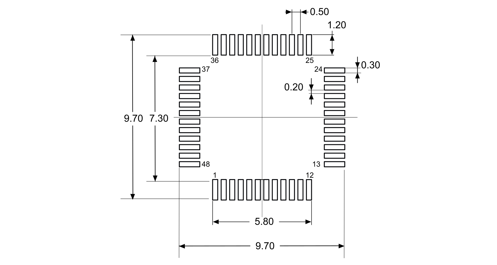
- Dimensions are expressed in millimeters.