This section describes the basic terms used on the displays and graphics context in order to provide an overview of the general display and graphics environment. This section also summarizes the display interfaces supported by the STM32 Arm-based MCUs.
Basic graphics concepts
This section describes a basic embedded graphic system, the display module categories and the display technologies.
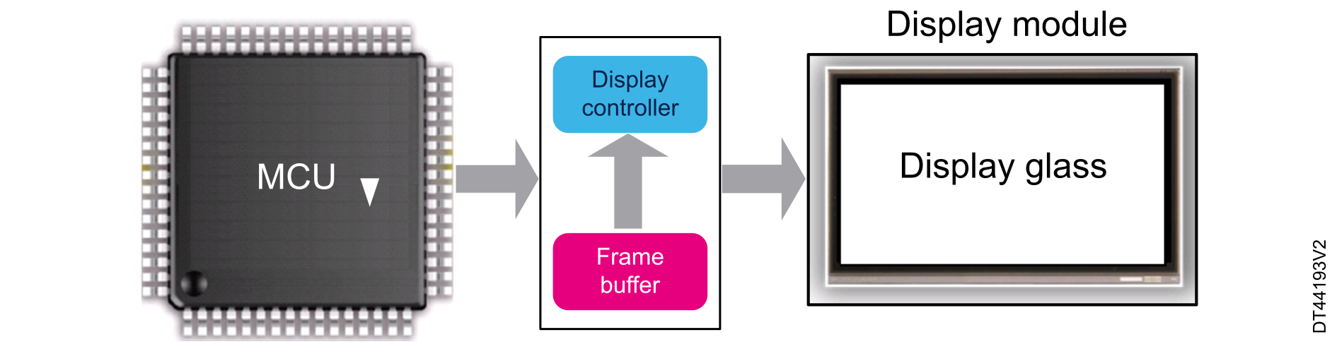
A basic embedded graphic system is composed of a microcontroller, a framebuffer, a display controller and a display glass.
The MCU computes the image to be displayed in the framebuffer, assembling graphical primitives such as icons or images. The CPU performs this operation by running a graphical library software. This process can be accelerated by a dedicated hardware like the DMA2D Chrom-Art Accelerator, used by the graphical library. The more often the framebuffer is updated, the more fluent the animations are (animation fps).
The framebuffer is a volatile memory used to store pixel data of the image to be displayed. This memory is usually called the graphic RAM (GRAM). The required size of the framebuffer depends on the resolution and color depth of the display. See Framebuffer memory size requirements and location for more information on the required size of the framebuffer.
Double buffering is a technique that uses double framebuffers to avoid displaying what is being written to the framebuffer.
The display controller is continuously “refreshing” the display, transferring the framebuffer content to the display glass 60 times per second (60 Hz). The display controller can be embedded either in the display module or in the MCU.
The display glass is driven by the display controller and is responsible to display the image that is composed of a matrix of pixels.
A display is characterized by:
Display size (resolution): is defined by the number of pixels of the display that is represented by horizontal (pixels number) x vertical (lines number).
Color depth: defines the number of colors in which a pixel can be drawn. It is represented in bits per pixel (bpp). For a color depth of 24 bpp (that can also be represented by RGB888) a pixel can be represented in 16777216 colors.
Refresh rate (in Hz): is the number of times per second that the display panel is refreshed. A display must be refreshed 60 times per seconds (60 Hz) since lower refresh rate creates bad visual effects.
Display module categories
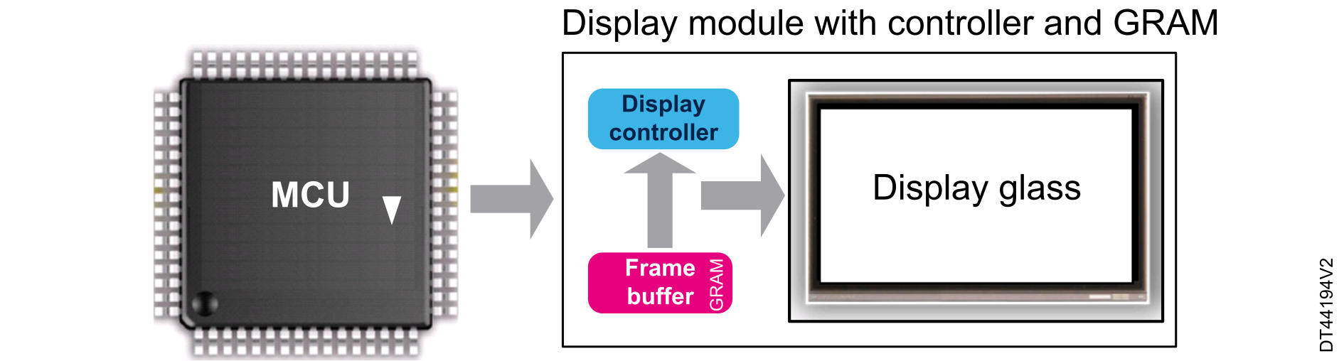
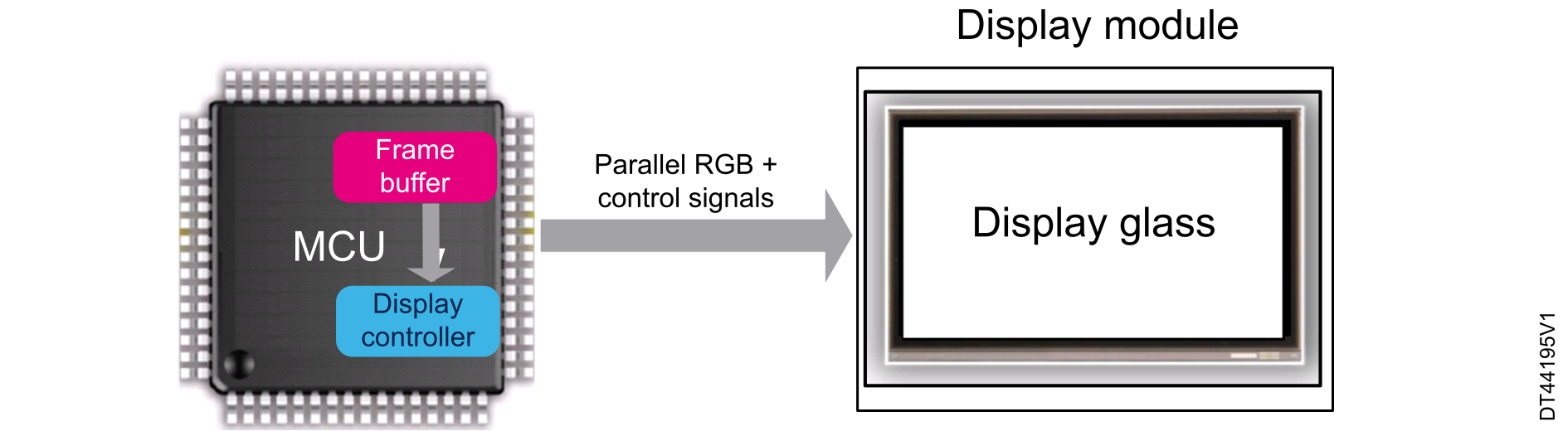
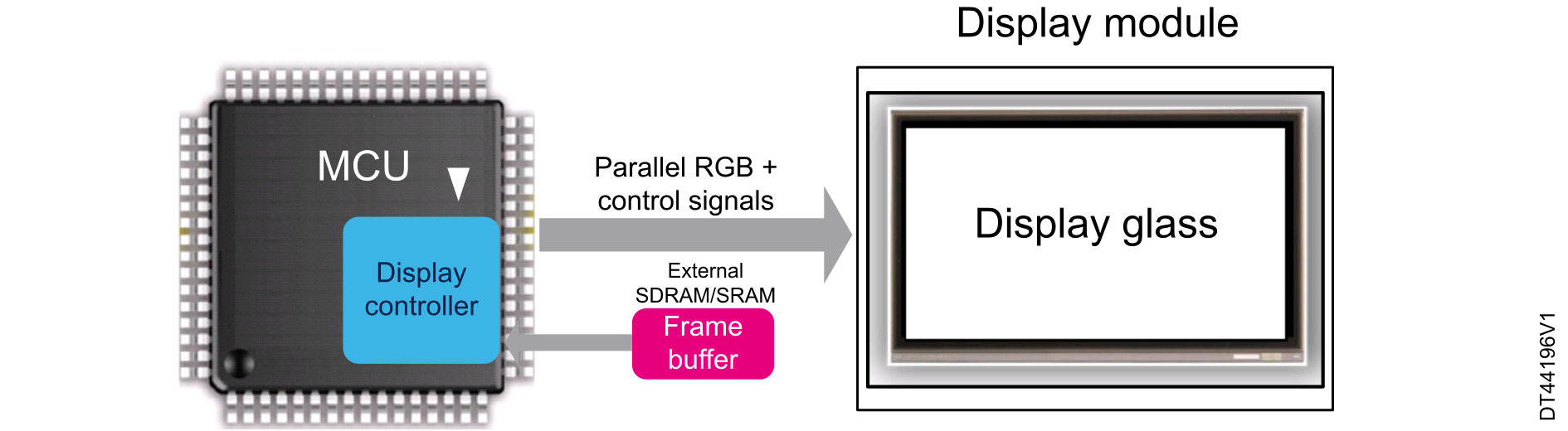
The display modules are classified in two main categories, depending on whether they embed or not an internal controller and a GRAM:
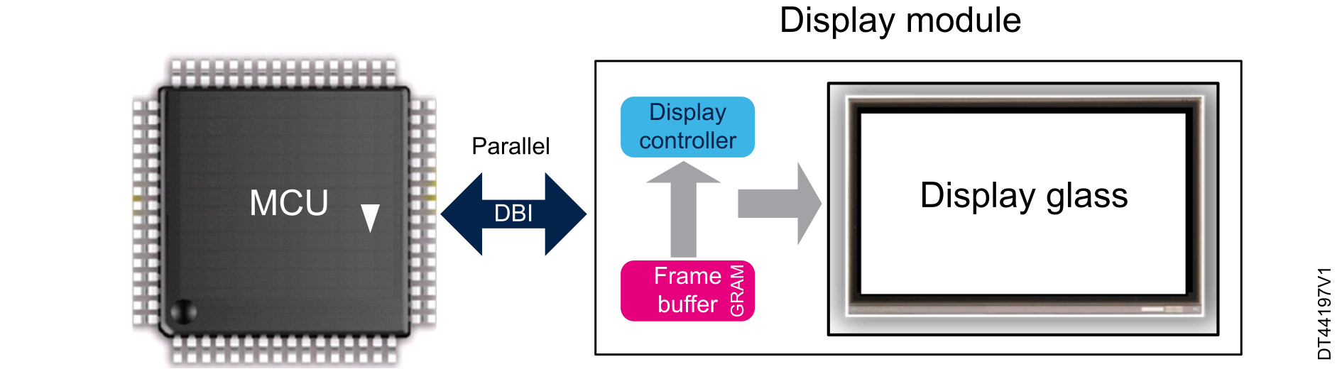
Figure 2. Display module with embedded controller and GRAM Figure 3. Display module without controller nor GRAM Figure 4. Display module without controller nor GRAM and with external framebuffer
Display technologies
There are many display technologies available on the market. The two main technologies used are described below:
LCD-TFT displays (liquid crystal display - thin film transistor): variant of LCD that uses the TFT technology to improve the control of each pixel. Thanks to the TFT technology, each pixel can be controlled by a transistor, allowing a fast response time and an accurate color control.
OLED displays (organic LED): pixels made of organic LEDs emitting directly the light, offering a better contrast and an optimized consumption. The OLED technology enables the possibility to use flexible displays, as no glass nor backlight are required. The response time is very fast and the viewing angle is free as it does not depend on any light polarization.
The way of driving the display module is quite similar in TFT and OLED technologies, the main difference is in the backlight requirement, as the OLED does not require any.
Display interface standards
The MIPI® (mobile industry processor interface) Alliance is a global, collaborative organization, committed to define and promote interface specifications for mobile devices. The MIPI Alliance develops new standards but also standardizes the existing display interfaces:
MIPI display bus interface (MIPI-DBI)
The MIPI-DBI is one of the first display standards published by the MIPI Alliance to specify the display interfaces. The three types of interfaces defined inside the MIPI-DBI are:
Type A: based on Motorola 6800 bus
Type B: based on Intel® 8080 bus
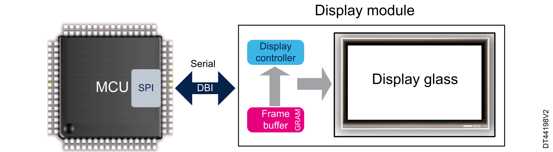
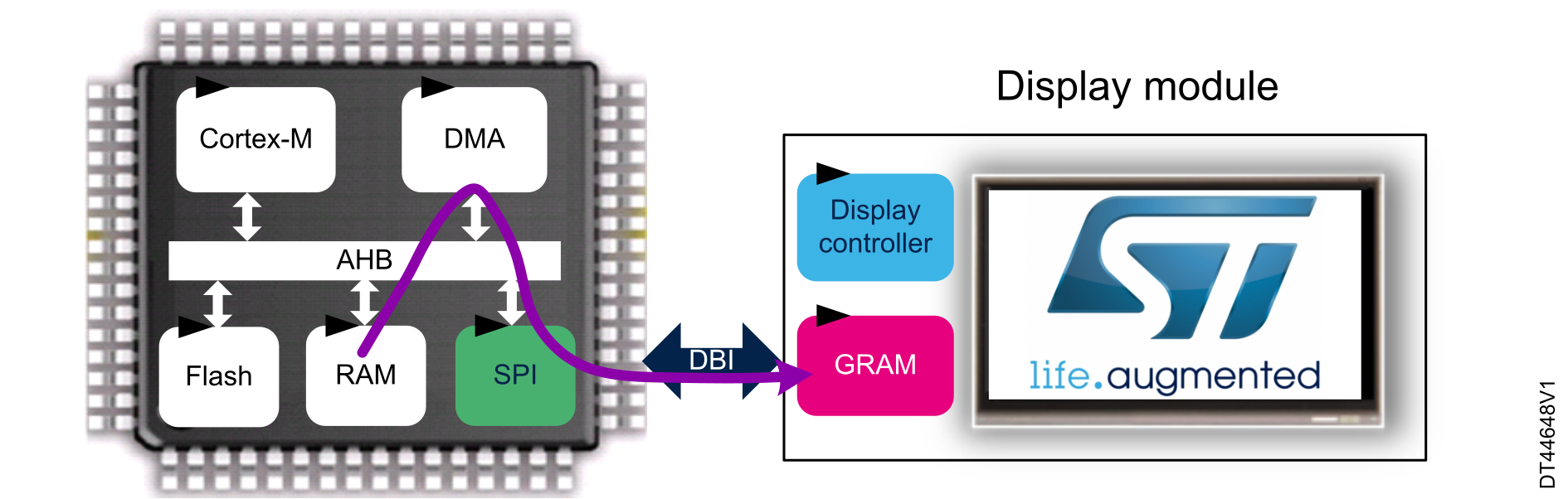
Type C: based on SPI protocol
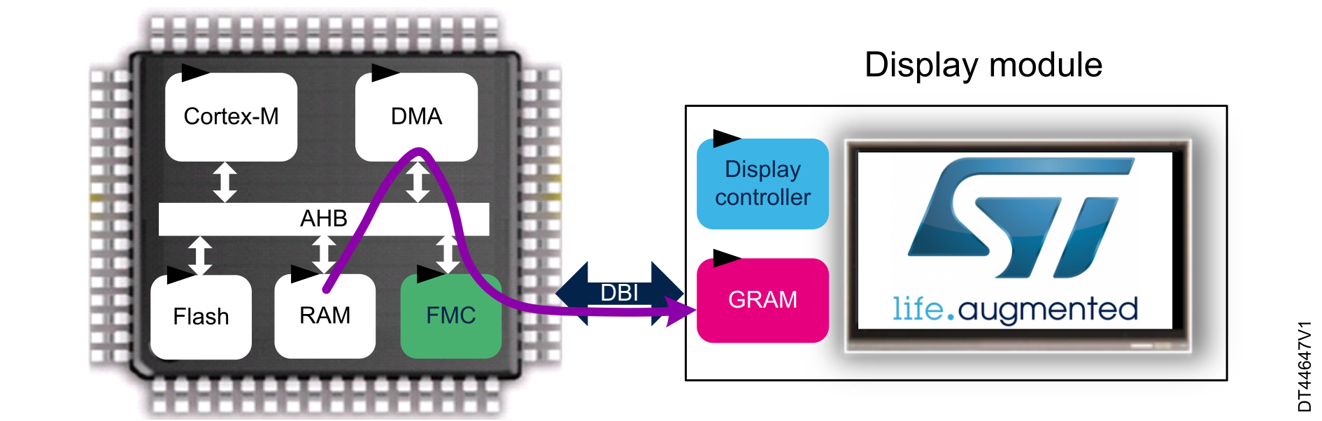
The MIPI-DBI is used to interface with a display with an integrated graphic RAM (GRAM). The pixel data is updated in the local GRAM of the display. Figure 5 MIPI-DBI type A or B interface illustrates a MIPI-DBI type A or B display interfacing example.
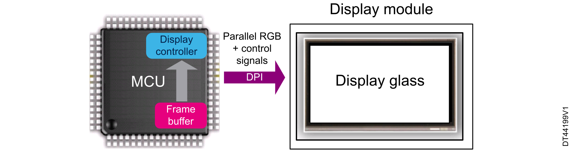
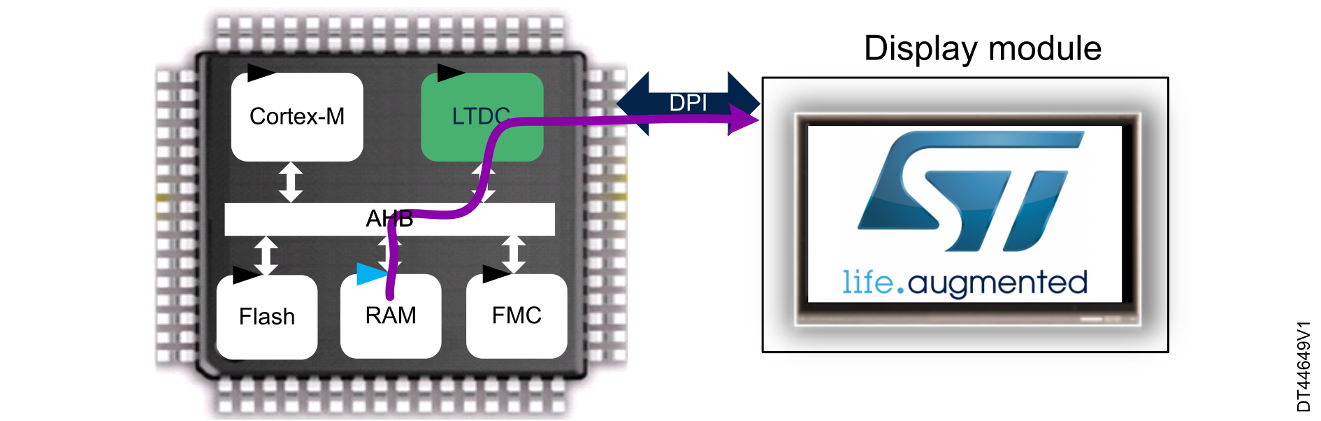
The DPI standardizes the interface through a TFT controller. An example is when using a 16-bit to 24-bit RGB signaling with synchronization signals (HSYNC, VSYNC, EN and LCD_CLK).
The DPI is used to interface with a display without a framebuffer. The pixel data must be streamed real time to the display.
The real-time performance is excellent but requires a high bandwidth in the MCU to feed the display.
Figure 7. MIPI-DPI interface
MIPI display serial interface (MIPI-DSI)
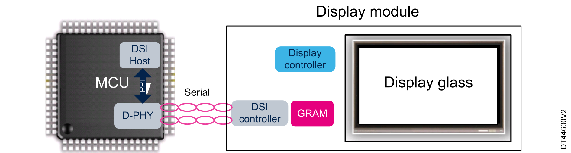
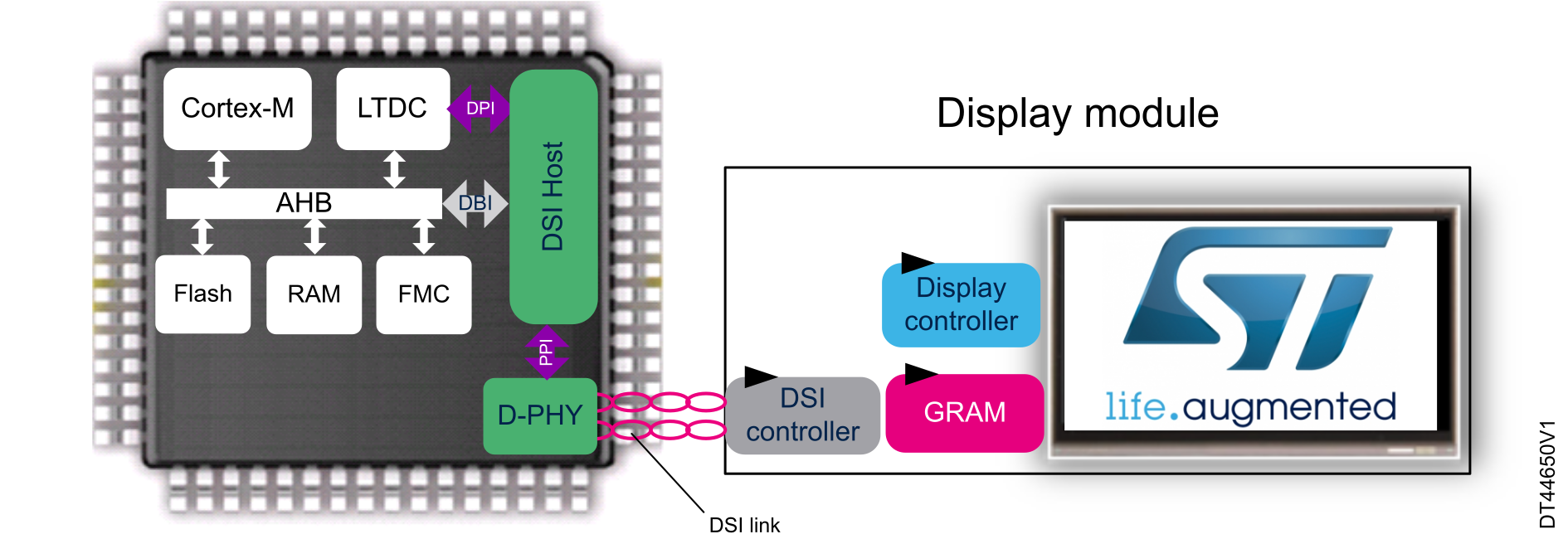
In order to decrease the number of lines to interface with a display, the MIPI Alliance has defined the DSI. The DSI is a high bandwidth multilane differential link; it uses standard MIPI D-PHY for the physical link.
The DSI encapsulates either DBI or DPI signals and transmits them to the D-PHY through the PPI protocol.
Figure 8. MIPI-DSI interface
Display interfaces supported by STM32 MCUs
Here below a summary on the MIPI Alliance display interfaces supported by STM32 MCUs:
All STM32 MCUs support the MIPI-DBI type C (SPI) interface.
All STM32 MCUs with F(S)MC support the MIPI-DBI type A and B interfaces.
STM32 MCUs with LTDC support the MIPI-DPI interface.
STM32 MCUs embedding a DSI Host support the MIPI-DSI interface.