製品概要
概要
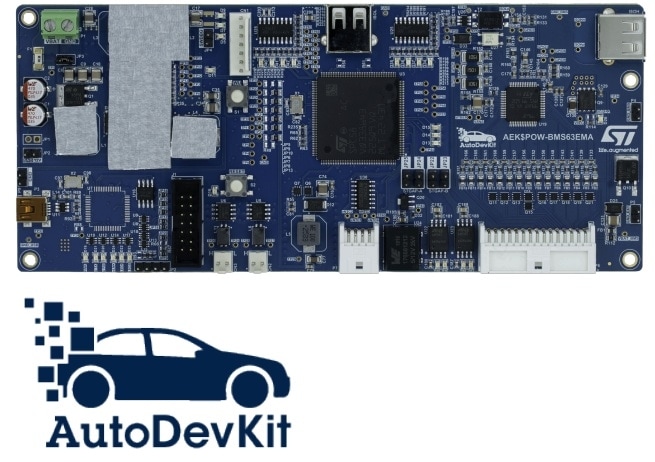
The AEK-POW-BMS63EM is a battery management system (BMS) evaluation board that can handle from 1 to 31 Li-ion battery nodes. Each battery node manages from 4 to 14 battery cells, for a voltage range from 48 to 64 V.

Thanks to the two embedded transceivers, the board can be used as the first node in a BMS daisy chain, connected to a battery pack of 6, or 10 (in configuration A or B, as detailed in UM3185), or 14 cells, and in a dual access ring BMS chain.
The board monitors state of charge (SoC) and state of health (SOH) of each battery and manages battery balancing by passive discharge, thanks to the software already preloaded on the on-board SPC58NN84E7 microcontroller.
The board is equipped with two CAN ports featuring the versatile CAN2.0 protocol that facilitates integration into several systems and efficient component communication.
It hosts the following devices: SPC58NN84E7, L9963F, L9963T, LM2902W, and STGAP2GS.
The SPC58NN84E7 automotive grade microcontroller is responsible for calculating the SoC and the SOH of the battery pack connected, based on the measurement provided by the L9963F through the L9963T ISOSPI<>SPI transceiver.
The power management integrated circuit (PMIC) supplies the entire board except for the BMS (first node) module only.
The PMIC consists of four DC/DC converters: three buck converters (5, 3.3 and 0.97 V) and one boost controller (9.5 V). In addition, it features two LDOs, both at 5 V.
The step-down converter 5 V output is used to power the microcontroller and other main peripherals such as the L9963T, while the LDO is used to power the microcontroller ADC. NVM procedure is also available but not exploited on this board. Thus, the default ST value is used.
Thanks to the L9963T transceiver, the MCU and the L9963F communicate through the ISOSPI protocol, implementing differential communication for higher noise immunity.
The L9963F is designed for operation in both hybrid (HEV) and full electric (BEV) vehicles using lithium battery packs, but its use can be extended to other transportation and industrial applications.
The main activity of the L9963F is monitoring cells and battery node status through stack voltage measurement, cell voltage measurement, temperature measurement, and coulomb counting.
Measurement and diagnostic tasks can be executed either on demand or periodically, with a programmable cycle interval. Measurement data are available for the onboard SPC58NN84E7 microcontroller to perform charge balancing and to compute the state of charge (SoC) and the state of health (SOH).
The L9963T general-purpose SPI to isolated SPI bidirectional transceiver can transfer incoming communication data from a classical 4-wire based SPI interface to a 2-wire isolated interface (and vice versa). In our board, the two transceivers are configured as slaves.
The LM2902W is used to sense the temperature in the battery ecosystem (that is, the temperature in the battery pack) through NTCs.
The STGAP2GS keeps the control circuit and power circuit electrically separate (isolated), increasing system safety, and robustness. It therefore protects the control section (for example, the microcontroller) from overvoltage or faults that may occur in the power section.
In our application, to connect different battery holders with a variable number of battery cells to the first node, we short-circuited the missing cells on the battery pack as well as the unused cells of the L9963F device, through MOSFETs driven by the STGAP2GS gate driver.
The unused cells are disabled via software to avoid incorrect readings of the remaining cells and the related diagnostics, and to prevent potential failures (such as cell undervoltage).
A standard BMS primarily monitors and protects the battery pack. The protection function brings the system to a safe state in case of under/overvoltage and overheating.
The board safety features include overload and overvoltage protection, against potential issues that could compromise battery integrity, alongside overdischarge protection to prevent excessive discharge and extend battery life.
The board core features ensure battery health and longevity. Continuous voltage monitoring provides real-time information about battery status, enabling quick detection of deviations from ideal voltage levels, ensuring reliability, and preventing potential issues.
The AEK-POW-BMS63EM provides an elaborate monitoring network to sense the voltage, current, and temperature of each cell. This sensing allows elaborating the SoC of each battery cell and, consequently, the state of charge of all battery packs. The SoC allows assessing the remaining battery capacity, which equates to the remaining driving range.
As previously mentioned, the AEK-POW-BMS63EM can work into two different topologies: daisy chain and dual access ring.
In the daisy chain configuration, a series of BMS is connected to the AEK-POW-BMS63EM, configured as the first node of the chain.
The onboard MCU communicates with the hosted L9963T transceiver through the SPI protocol. The transceiver converts these signals into ISO SPI signals to communicate with the other BMS nodes of the chain.
Converting SPI signals into isolated SPI signals, the transceiver reduces the number of necessary wires from 4 to 2 and implements differential communication for higher noise immunity.
A dual-access ring configuration is also possible thanks to the second onboard transceiver that makes the communication bidirectional. The secondary ring is used as a backup in case the primary ring fails. Data moves in opposite directions around the rings, and each ring remains independent of the other unless the primary ring fails. The two rings are connected to continue the flow of data traffic.
In our application, the AEK-POW-BMS63EM is the first node of the chain, while the additional nodes can be other BMS boards of our portfolio.
In the AutoDevKit ecosystem software package, we developed an example demo application based on the SPC58NN84E7 MCU for dual access ring configuration to estimate the SoC of 14 cells in a BMS node connected to an AEK-POW-BMS63EM evaluation board, using Li-ion batteries (LG INR 18650 MJ1).
The results of SoC estimation, cell voltage, battery pack temperatures and current can be printed via the serial port to a terminal on the PC with a speed rate of 115200 bps.
-
機能一覧
- Hosts:
- L9963F AEC-Q100 qualified automotive multicell battery monitoring and balancing IC
- Two L9963T AEC-Q100 qualified automotive general-purpose SPI to isolated SPI bidirectional transceivers
- Two CAN-FD transceivers supporting high-speed applications up to 8 Mbps
- SPC58NN84E7 ASIL-D MCU, featuring five cores and a hardware security module for system robustness, safety and integrity, to perform charge balancing and to compute the state of charge (SoC) and the state of health (SOH)
- Two STGAP2GS isolated gate drivers to isolate the microcontroller from overvoltage or faults and to allow different battery pack connections by driving the MOSFETs that short-circuit unused cells
- LM2902W low-power quad operational amplifier to sense the battery pack temperature
- Four battery pack connections are possible with 6, or 10 (in configuration A or B), or 14 cells, using the AEK-POW-BMS63EM as first node
- Voltage monitoring of up to 14 battery cells
- Current sensing of the entire battery node
- Thanks to the two embedded L9963T ISOSPI transceivers, the board allows configuring two different topologies: daisy chain and dual access ring
- 4 configurable GPIOs, pluggable with NTCs for temperature measurement through an external temperature sensor
- 3 embedded NTCs to sense the BMS node temperature
- 3 additional NTCs hosted on the battery holder connector
- SPI interface to communicate with the MCU
- Passive balancing
- JTAG module for board firmware debugging/programming
- Debug mode for board testing
- Compact size: 183 x 78 mm
- Included in the AutoDevKit ecosystem
- Hosts:
推奨コンテンツ
すべてのリソース
| Resource title | Version | Latest update | Actions | Details | ダウンロード |
|---|
Board Manufacturing Specifications (1)
| Resource title | Version | Latest update | Actions | Options | ||
|---|---|---|---|---|---|---|
| ZIP | 1.0 | 04 Jun 2026 | 04 Jun 2026 |
BOM (1)
| Resource title | Version | Latest update | Actions | Options | ||
|---|---|---|---|---|---|---|
| 1.0 | 04 Jun 2026 | 04 Jun 2026 |
Schematic Pack (1)
| Resource title | Version | Latest update | Actions | Options | ||
|---|---|---|---|---|---|---|
| 1.0 | 04 Jun 2026 | 04 Jun 2026 |
Quality and Reliability
| Part Number | Marketing Status | Package | Grade | RoHSコンプライアンスグレード | WEEE Compliant | Longevity Commitment | Longevity Starting Date | Material Declaration** |
|---|---|---|---|---|---|---|---|---|
| AEK-POW-BMS63EM | Active 交換品交換品 | CARD | Industrial | Ecopack2 | Yes | - | - | |
AEK-POW-BMS63EM
Package:
CARDMaterial Declaration**:
(**) st.comで提供している材料宣誓書は、パッケージ・ファミリ内で最も一般的に使用されているパッケージに基づく汎用ドキュメントの場合があります。そのため、特定の製品では100%正確ではない可能性があります。特定の製品情報については、セールスサポートまでお問い合わせください

You’re now leaving st.com and will be re-directed to our Partner’s website.
For the latest innovations and solutions from ST, sign up for our newsletters.
Sample & Buy


| Part Number | 製品ステータス | Budgetary Price (US$)*/Qty | STから購入 | Order from distributors | Package | Packing Type | RoHS | Country of Origin | ECCN (US) | ECCN (EU) | Supplier | Core Product | |
|---|---|---|---|---|---|---|---|---|---|---|---|---|---|
| AEK-POW-BMS63EM | | | distributors 販売代理店に在庫がない場合は、STのセールス・オフィスまでお問い合わせください |
|
|
AEK-POW-BMS63EM Active
販売代理店に在庫がない場合は、STのセールス・オフィスまでお問い合わせください
(*)概算用の参考価格(US$)です。現地通貨でのお見積りについては、STのセールス・オフィスまたは販売代理店までお問い合わせください。