製品概要
概要
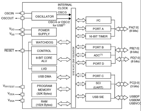
The ST7263B microcontrollers form a sub-family of the ST7 MCUs dedicated to USB applications. The devices are based on an industry-standard 8-bit core and feature an enhanced instruction set. They operate at a 24 MHz or 12 MHz oscillator frequency. Under software control, the ST7263B MCUs may be placed in either Wait or Halt modes, thus reducing power consumption. The enhanced instruction set and addressing modes afford real programming potential. In addition to standard 8-bit data management, the ST7263B MCUs feature true bit manipulation, 8x8 unsigned multiplication and indirect addressing modes. The devices include an ST7 Core, up to 32Kbytes of program memory, up to 1024 bytes of RAM, 27 I/O lines and the following on-chip peripherals:
The ST72F63B devices are Flash versions. They support programming in IAP mode (in-application programming) via the on-chip USB interface.
-
機能一覧
- 2 communication Interfaces
Asynchronous serial communications Interface I2C multimaster Interface up to 400 kHz - 2 timers
Programmable watchdog 16-bit timer with 2 Input Captures, 2 Output Compares, PWM output and clock input - Development tools
Versatile development tools (under Windows) including assembler, linker, C-compiler, archiver, source level debugger, software library, hardware emulator, programming boards and gang programmers, HID and DFU software layers - Memories
4, 8, 16 or 32 Kbytes program memory: high density Flash (HDFlash), FastROM or ROM with Read-Out and Write protection In-application programming (IAP) and in-circuit programming (ICP) 384, 512 or 1024 bytes RAM memory (128-byte stack) - USB (universal serial bus) Interface
DMA for low speed applications compliant with USB 1.5 Mbs (version 2.0) and HID specifications (version 1.0) Integrated 3.3 V voltage regulator and transceivers Supports USB DFU class specification Suspend and Resume operations 3 endpoints with programmable Input/Output configuration - Clock, reset and supply management
Run, Wait, Slow and Halt CPU modes 12 or 24 MHz oscillator RAM Retention mode Optional low voltage detector (LVD) - 1 analog peripheral
8-bit A/D converter with 8 or 12 channels - Instruction Set
63 basic instructions 17 main addressing modes 8 x 8 unsigned multiply instruction True bit manipulation - Up to 27 I/O ports
Up to 8 high sink I/Os (10 mA at 1.3 V) 2 very high sink true open drain I/Os (25 mA at 1.5 V) Up to 8 lines individually programmable as interrupt inputs
- 2 communication Interfaces
回路ダイアグラム
EDA Symbols, Footprints and 3D Models
STMicroelectronics - ST7263BH6
Speed up your design by downloading all the EDA symbols, footprints and 3D models for your application. You have access to a large number of CAD formats to fit with your design toolchain.
Please select one model supplier :
Symbols

Footprints

3D models
すべてのリソース
| Resource title | Version | Latest update | Actions | Details | ダウンロード |
|---|
Board Manufacturing Specifications (1)
| Resource title | Version | Latest update | Actions | Options | ||
|---|---|---|---|---|---|---|
| ZIP | 1.0 | 01 Aug 2015 | 01 Aug 2015 |