降圧レギュレータ(DC-DC降圧スイッチング・レギュレータ)は、入力電圧を降圧し、安定した出力電圧を提供するDC-DCコンバータです。
STのモノリシック降圧レギュレータICは、最大61Vの入力電圧および最大4Aの出力電流を高いスイッチング周波数で供給します。
STの降圧レギュレータは、過電流、過電圧、過熱保護などの包括的な保護機能を搭載しているため、平均故障間隔(MTBF)の延長、必要な外付け部品数の削減、その結果としての部品(BOM)コストの低減に貢献します。
さまざまなアプリケーション要件に対応するモノリシック降圧レギュレータIC
製品タイプ:適切な降圧レギュレータを選択する方法
幅広い要件に対応可能なSTの降圧レギュレータのラインアップをご紹介します。


低消費電力降圧コンバータは、低負荷時の超低静止電流と高い効率を特徴としているため、これらのアプリケーション要件を満たします。
ただし、EMI規格への適合を難しくするだけでなく、ノイズの影響を受けやすいアプリケーションに干渉する可能性もあるスイッチング・ノイズがもたらされます。
低ノイズ降圧コンバータは、設計者がこれらの課題に対処するために役立ちます。


短いオン時間により、入力から出力への大きな変換率を確保しながらも、高いスイッチング周波数が維持されます。
メリット
- 高い信頼性、堅牢性、および省スペースを備えた高電圧テクノロジー
- 高性能であらゆる負荷における高効率を実現するコンスーマおよびコンピュータ機器向け製品
注目ビデオ
High efficiency and performance 6 V, 6 A step-down synchronous switching regulator for automotive applications
The DCP0606Y is an AEC-Q100 Grade 1 qualified step-down converter designed to meet the demanding requirements of automotive applications.
Capable of delivering a continuous output current of up to 6 A, the device features overvoltage, overcurrent, and overtemperature auto-recovery protections, making it ideal for high current, and low voltage post-regulation.
Housed in a compact QFN 2x3 mm package with wettable flanks, the DCP0606Y is suitable for space-constrained applications like: ADAS power supply, telematics, HUD, infotainment, multimedia, and camera digital core power supply.
Developers can be supported in their designs by the STEVAL-0606YADJ product evaluation board.
Synchronous buck converters for industrial applications
The DCP3601 (up to 1 A load current) and the DCP3603 (up to 3 A load current) are versatile, efficient, and reliable synchronous step-down converter suitable for a wide range of applications like major appliances, smart metering, and industrial 24 V bus conversion.
Their comprehensive feature set, including wide input voltage range, high efficiency, advanced protection features, and compact size, makes them the right choice for engineers looking to optimize their power conversion designs.
Both devices are available in two versions, LCM (Low Current Mode) for high efficiency at light loads and LNM (Low Noise Mode) for noise-sensitive applications; developers can also be supported in their designs by the STEVAL-3601CV1 and STEVAL-3603BC1 evaluation boards.
38 V, 3A synchronous buck converters for automotive applications
Nowadays, automotive systems require robustness, low consumption, high efficiency, and small size, especially for the vehicle electrification.
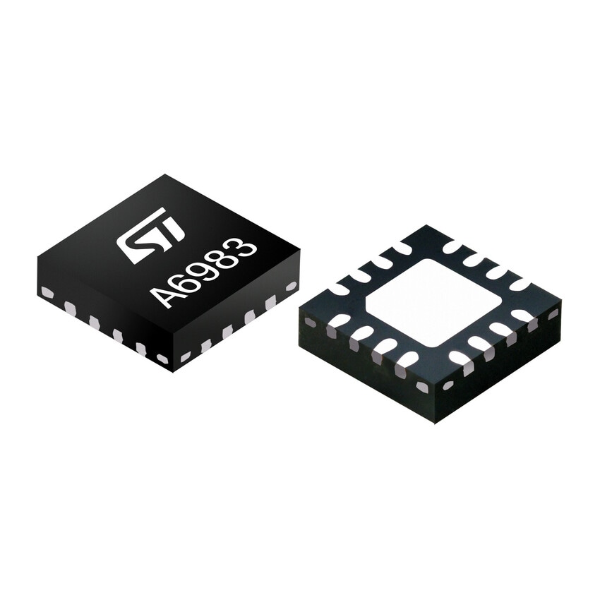
The A6983 is an AEC-Q100 qualified synchronous step-down converter suitable for battery-powered applications, car body applications, smart ambient lighting system supply, and car audio and low noise applications.
The A6983I is an AEC-Q100 qualified synchronous iso-buck converter specifically designed for isolated buck topology. It is particularly suitable for electric traction systems, OBC (on-board charger) for HEV/EV and automotive isolated IGBT/SiC MOSFET gate drive supply.
The STEVAL-A6983CV1, STEVAL-A6983NV1, and STEVAL-L6983IV1 evaluation boards are available to support developers in their designs.
L6983I: synchronous iso-buck converter for isolated applications
A floating-voltage source, which is the main target application of the isolated buck topology, is commonly requested to provide supply to high-side gate drivers in high-power DC-DC converters, inverters, motor drivers, and other industrial applications.
The L6983I, specifically designed for isolated buck topology, provides a flexible, reliable, and easy-to-use solution for isolated IGBT/SiC/GaN MOSFET gate drive supplies, on-board chargers (OBC) for HEV/EV, and electric traction systems.
About buck converters
How does a buck converter work?
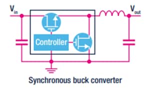
A buck converter usually uses two switches and an inductor to make a voltage controlled current source that interacts with the parallel combination of output capacitor and load, to generate the desired output voltage (VOUT < VIN).
Where and why is a buck converter used?
A buck converter is used to step down the voltage of a given input to achieve the required output voltage. Buck converters can be used in many applications, including smartphones, tablets, battery-powered equipment, industrial power systems and point-of-load supplies.
What are the advantages of a buck converter?
Buck converters offer a more efficient solution with fewer, smaller external components. They can step-down voltages using a minimal number of components. In the same time, they offer a lower operating duty cycle and higher efficiency across a wide range of input and output voltages.
eDesignSuite
eDesignSuiteは、幅広いST製品を用いたシステム開発プロセスの効率化を支援する、使いやすい設計支援ユーティリティの包括的なセットです。


パワー・マネージメント設計センター
デバイス用熱電気シミュレータ
シグナル・コンディショニング設計ツール
NFC / RFIDカリキュレータ

電源設計ツール

LED照明設計ツール

デジタル電源ワークベンチ

パワー・ツリー・デザイナ

STPOWER Studio

PCB熱シミュレータ

ACスイッチ・シミュレータ

整流ダイオード・シミュレータ

TwisterSim

TVSシミュレータ

Estimate

アクティブ・フィルタ

コンパレータ(ウィンドウ・コンパレータ機能搭載)

ローサイド電流センス・アンプ

ハイサイド電流センス・アンプ

NFCインダクタンス

UHFリンク・バジェット


