 |  |
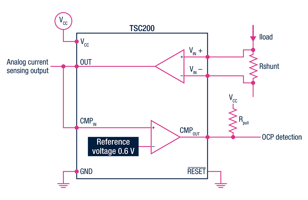
Integrated OCP:
| Op amp OCP:
|
How to choose the right current sense amplifier for your design
Understanding these parameters is essential to select the right current sensor for your application to optimize system performance.
Key parameters for choosing a current sensing amplifier
When selecting a current sensing amplifier, the following parameters are critical:
Input common voltage
Load current range
Current direction flowing into the load
- Input common-mode voltage (Vicm):
The voltage range at the input pins is relative to ground. Extended Vicm allows sensing in high-voltage environments such as automotive 48 V systems. - Load Current Range:
The expected range of current to be measured. - Current Direction:
Whether unidirectional or bidirectional current measurement is required.
Define the configuration required for your device
- High-side configuration
Select the current sense amplifier depending on the max common mode voltage (VICM) required by the application and its power supply (VCC). - Low-side configuration:
Select a current sense amplifier that can work with a common-mode voltage close to 0 volts. Operational amplifiers can be also used, adding 4 external resistors to set the gain. However, the size of the PCB will be larger, and accuracy can be lower.
Look into the direction of current flows
After defining the configuration required, ask yourself if the current in your application needs to flow in both directions, to choose a bidirectional or unidirectional current sensing.
If accurate measurements are needed
Several parameters related to the application must be considered. Depending on the current range to be measured and the shunt resistor used, the voltage drop into the shunt resistor can be very small (hundreds of µV). For better accuracy, it is important to consider the error related to offset and accuracy gain.
Show More
Show Less
Our current sensing solution involves a shunt resistor and Ohm's law to obtain an accurate current measurement. Shunt resistors dissipate power in the form of heat, which affects measurement precision. Lower shunt resistance minimizes the impact, but higher amplification gain is required, which lowers overall measurement precision.
.jpg)
Errors and calibration in current sensing
Accurate current sensing is critical in many electronic applications, from power management to motor control and battery monitoring. However, achieving precise current measurement is often challenged by various sources of error. Understanding these common errors and applying proper calibration techniques can significantly enhance measurement accuracy and system reliability.
Common errors in current sensing
Offset errors
Offset errors arise from inherent voltage offsets in amplifiers or sensors, causing a non-zero output even when no current flows. This leads to baseline inaccuracies that distort low-level current measurements.
Gain errors
Gain errors occur when the sensor’s output does not scale linearly with the input current due to component tolerances or temperature variations. This results in proportional measurement inaccuracies across the sensing range.
Temperature drift
Components such as shunt resistors and amplifiers change their characteristics with temperature, causing measurement drift. This can lead to errors that vary with operating conditions.
Parasitic resistances and inductances
PCB traces, connectors, and wiring add unintended resistance and inductance, which can skew current measurements, especially at high frequencies or transient conditions.
Calibration techniques to reduce errors
Offset calibration
Perform zero-current calibration by measuring the sensor output with no current flow, and subtracting this offset from subsequent readings. This corrects baseline errors and improves low-level accuracy.
Gain calibration
Apply known reference currents and adjust the sensor gain to align the output with expected values. This compensates for gain errors.
Temperature compensation
Use temperature sensors to monitor the environment and apply correction algorithms or select components with low temperature coefficients to minimize drift.
Filtering and Shielding
Implement analog or digital filtering to reduce noise and use proper shielding and grounding techniques to mitigate EMI and interference.
Regular recalibration
Periodically recalibrate the system to account for component aging, environmental changes, and mechanical stresses that may alter sensor characteristics.
Integrated overcurrent protection (OCP) vs. operational amplifier
One of the key points in preventing damage in an application is the ability to measure current variations very quickly and accurately. Current sensing with a comparator circuit is a method commonly used to detect an overcurrent. In many applications with input common-mode voltage below 30 V, the choice between a current sense monitor or operational amplifier is a matter of designer preference.