A buck converter, also called buck regulator or DC-DC step-down switching regulator, is a type of DC-DC converter that provides an output regulated voltage that is lower than its input voltage.
ST's monolithic step-down (buck) converter ICs offer input-voltage capability up to 61 V and deliver output currents up to 4 A with high switching frequency.
These buck regulators embed a full set of protection functions (overcurrent, overvoltage, and over-temperature) to increase the mean time between failures (MTBF) and reduce the number of external components required, thus lowering BOM costs.
Monolithic buck converter ICs (buck regulator) for any application requirement

Applications
Buck converters can be used for a large number of applications.

- ST offers high performance and high flexibility AEC-Q100 compliant buck converters for automotive applications.
- See all Automotive buck converters
- High reliability and excellent robustness buck converters, for industrial and any application requiring a wide range of input output voltages.
- See all Industrial buck converters
Product types: how to choose the right buck converter
Learn about ST broad selection of buck converters, designed to meet a wide range of requirements.


Low-consumption buck converters feature ultra-low quiescent current and high efficiency at light load to meet these application requirements.
However, they also introduce switching noise that could represent a big obstacle to comply with EMI standards and disturb noise-sensitive applications.
Low-noise buck converters help designers meet these challenges.


A short on-time ensures a large input-to-output conversion ratio while maintaining a high switching frequency.
Benefits
- High-voltage technology together with high reliability, robustness, and compactness
- High efficiency at any load and a high level of performance for consumer and computer products
Featured Videos


Recommended for you
High efficiency and performance 6 V, 6 A step-down synchronous switching regulator for automotive applications
The DCP0606Y is an AEC-Q100 Grade 1 qualified step-down converter designed to meet the demanding requirements of automotive applications.
Capable of delivering a continuous output current of up to 6 A, the device features overvoltage, overcurrent, and overtemperature auto-recovery protections, making it ideal for high current, and low voltage post-regulation.
Housed in a compact QFN 2x3 mm package with wettable flanks, the DCP0606Y is suitable for space-constrained applications like: ADAS power supply, telematics, HUD, infotainment, multimedia, and camera digital core power supply.
Developers can be supported in their designs by the STEVAL-0606YADJ product evaluation board.
Synchronous buck converters for industrial applications
The DCP3601 (up to 1 A load current) and the DCP3603 (up to 3 A load current) are versatile, efficient, and reliable synchronous step-down converter suitable for a wide range of applications like major appliances, smart metering, and industrial 24 V bus conversion.
Their comprehensive feature set, including wide input voltage range, high efficiency, advanced protection features, and compact size, makes them the right choice for engineers looking to optimize their power conversion designs.
Both devices are available in two versions, LCM (Low Current Mode) for high efficiency at light loads and LNM (Low Noise Mode) for noise-sensitive applications; developers can also be supported in their designs by the STEVAL-3601CV1 and STEVAL-3603BC1 evaluation boards.
Synchronous buck converters for automotive applications
Nowadays, automotive systems require robustness, low consumption, high efficiency, and small size, especially for the vehicle electrification.
The A6983 and A6986 are AEC-Q100 qualified synchronous step-down converters suitable for battery-powered applications, car body applications, smart ambient lighting system supply, car audio, and low noise applications.
The A6983I and A6986I are AEC-Q100 qualified synchronous iso-buck converter specifically designed for isolated buck topology. To manage higher power and optimize the transformer, both A6986I and A6983I devices can be used in isolated buck-boost topology as well. They are particularly suitable for electric traction systems, OBC (on-board charger) for HEV/EV and automotive isolated IGBT/SiC MOSFET gate drive supply.
The STEVAL-A6983IV1, STEVAL-A6986IV3, STEVAL-A6983CV1, STEVAL-A6983NV1, and STEVAL-6986YT2DL evaluation boards are available to support developers in their designs.
L6983I: synchronous iso-buck converter for isolated applications
A floating-voltage source, which is the main target application of the isolated buck topology, is commonly requested to provide supply to high-side gate drivers in high-power DC-DC converters, inverters, motor drivers, and other industrial applications.
The L6983I, specifically designed for isolated buck topology, provides a flexible, reliable, and easy-to-use solution for isolated IGBT/SiC/GaN MOSFET gate drive supplies, on-board chargers (OBC) for HEV/EV, and electric traction systems.
The STEVAL-L6983IV1 evaluation board is available to support developers in their designs.
About buck converters
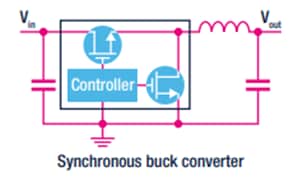
How does a buck converter work?
A buck converter usually uses two switches and an inductor to make a voltage controlled current source that interacts with the parallel combination of output capacitor and load, to generate the desired output voltage (VOUT < VIN).
Where and why is a buck converter used?
A buck converter is used to step down the voltage of a given input to achieve the required output voltage. Buck converters can be used in many applications, including smartphones, tablets, battery-powered equipment, industrial power systems and point-of-load supplies.
What are the advantages of a buck converter?
Buck converters offer a more efficient solution with fewer, smaller external components. They can step-down voltages using a minimal number of components. In the same time, they offer a lower operating duty cycle and higher efficiency across a wide range of input and output voltages.
eDesignSuite
eDesignSuite is a comprehensive set of easy-to-use design-aid utilities ready to help you streamline the system development process with a wide range of ST products.

Power Management Design Center
Thermal-electrical Simulators for Components Test
Signal Conditioning Design Tool
NFC/RFID Calculators
Power Management Design Center

Power Supply Design Tool Test
Power Management Design Center

LED Lighting Design Tool
Power Management Design Center

Digital Power Workbench
Power Management Design Center

Power Tree Designer
Thermal-electrical Simulators for Components Test

STPOWER Studio
Thermal-electrical Simulators for Components Test

PCB Thermal Simulator
Thermal-electrical Simulators for Components Test

AC Switches Simulator test
Thermal-electrical Simulators for Components Test

Rectifier Diodes Simulator test
Thermal-electrical Simulators for Components Test

Twister Sim
Thermal-electrical Simulators for Components Test

TVS Simulator
Thermal-electrical Simulators for Components Test
Estimate
Signal Conditioning Design Tool

Active Filters
Signal Conditioning Design Tool

Comparators
Signal Conditioning Design Tool

Low side Current Sensing
Signal Conditioning Design Tool

High side Current Sensing
NFC/RFID Calculators

NFC Inductance
NFC/RFID Calculators

UHF Link Budget
NFC/RFID Calculators
